Modern microcontrollers provide an amazingly diverse selection of hardware peripherals, all within a single chip. One needs to provide a small amount of supporting hardware to power the chip and connect its peripheral devices to the signals of interest and, when powered up, these devices need to be configured and monitored by a suitable firmware program. These notes focus on programming the 28-pin PIC18F26K22 microcontroller and its 40-pin PIC18F46K22 sibling, the 16-bit PIC24FV32KA302 and the 8-bit AVR ATmega328P. These microcontrollers are all available in plastic DIP packages, can be run from a 5 volt supply, and can be built into very simple prototype hardware. A number of example programs, in the Forth language, are provided to illustrate the use of some of each microcontroller’s peripheral devices. The examples cover the very simple "flash a LED" exercise through to driving a character-based LCD via its 4-bit parallel interface. Communication with SPI and I2C devices is also covered, with a common set of words being used to abstract away the differences between microcontrollers in terms of detailed bits and registers.
1. A selection of microcontrollers
Over the past couple of decades, microcontrollers have evolved to be cheap, powerful computing devices that even Mechanical Engineers can use in building bespoke instrumentation for their research laboratories. Typical tasks include monitoring of analog signals, sensing pulses and providing timing signals. Of course these things could be done with a modern personal computer connected via USB to a commercial data acquisition and signal processing system but there are many situations where the small, dedicated microcontroller, requiring just a few milliamps of current, performs the task admirably and at low cost.
Modern microcontrollers provide an amazingly diverse selection of hardware peripherals, all within a single chip. One needs to provide a small amount of supporting hardware to power the chip and connect its peripheral devices to the signals of interest and, when powered up, these devices need to be configured and monitored by a suitable firmware program. These following sections provide an introduction to the details of doing this with an 8-bit Microchip PIC18F26K22 or PIC18F46K22 microcontroller, a 16-bit PIC24FV32KA302 microcontroller and an 8-bit ATmega328P microcontroller, all programmed with the FlashForth version 5 interpreter.
Within each family of Microchip or Atmel microcontrollers, the individual microcontroller units (MCUs) all have the same core, i.e. same instruction set and memory organisation. Your selection of which MCU to actually use in your project can be based on a couple of considerations. If you are on a tight budget and will be making many units, choose an MCU with just enough functionality, however, if convenience of development is more important, choose one with "bells and whistles". For this tutorial guide, we will value convenience and so will work with microcontrollers that have:
-
a nice selection of features, including a serial port, several timers and an analog-to-digital converter. See the feature list and the block diagram of the PIC18F26K22 and PIC18F46K22 MCUs on the following pages.
-
a 28-pin narrow or 40-pin DIL package, which is convenient for prototyping and has enough I/O pins to play without needing very careful planning.
-
an ability to work as 3.3V or 5V systems.
-
a pinout as shown at the start of the datasheets (books) for each of the microcontrollers. You will be reading the pages of these books over and over but we include the following couple of pages from the PIC18F26K22/PIC18F46K22 datasheet to give an overview.
-
an internal arrangement that is built around an 8-bit or 16-bit data bus.
-
the ``Harvard architecture'' with separate paths and storage areas for program instructions and data.
We won’t worry too much about the details of the general-purpose registers, the internal static RAM or the machine instruction set because we will let the FlashForth interpreter handle most of the details, however, memory layout, especially the I/O memory layout is important for us as programmers. The peripheral devices, which are used to inferface with the real world, are controlled and accessed via registers in the data-memory space.


2. Development boards
This tutorial is based around simple support hardware for each of the microcontrollers. If you don’t want to do your own soldering, there are easy-to-buy demonstration boards available as a convenient way to get your hardware up and going. If you are a student of mechatroncis, however, you must eventually design and build your own hardware. The strip-board versions are aimed at you.
2.1. PIC18 family boards
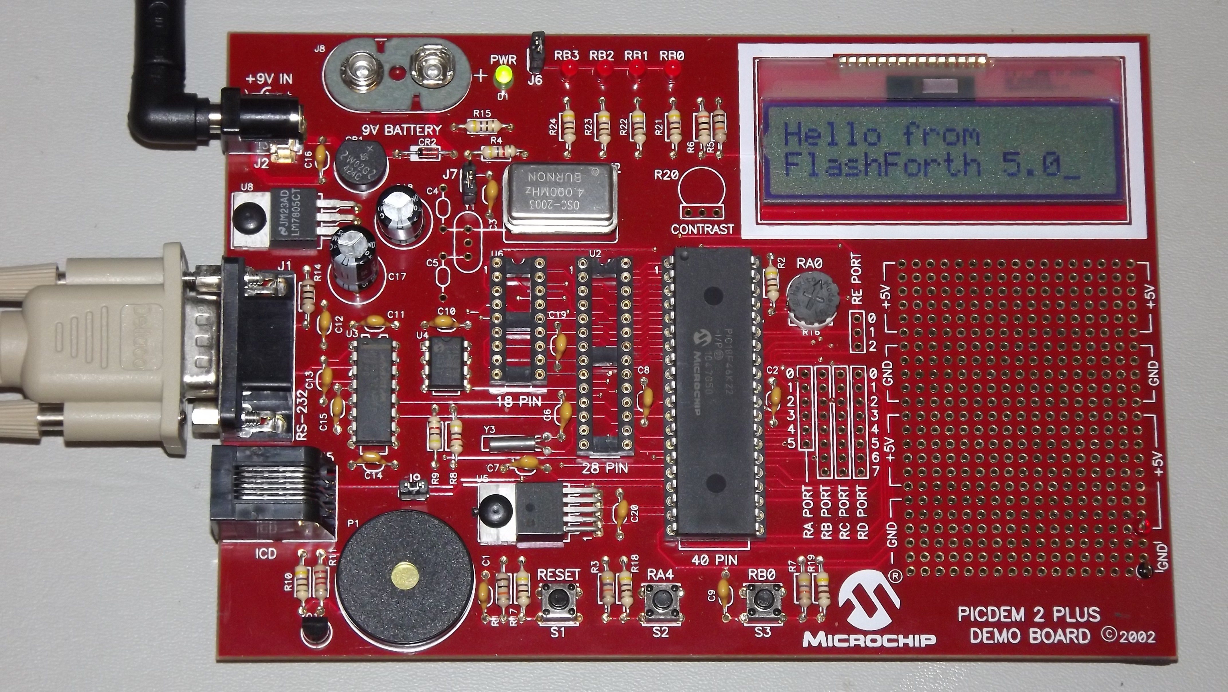
Here is a picture of PICDEM 2 PLUS with PIC18F46K22-I/P in the 40-pin socket (U1) and running the LCD, as described in a later section. We’ll make use of the serial RS-232 interface (MAX232ACPA, U3) to both program Forth application and to communicate with running applications. Other conveniences include on-board LEDs, switches, a potentiometer (RA0) and I2C devices, such as a TC74 temperature sensor (U5), just below the MCU and a 24LC256 serial EEPROM (U4). Initial programming of the FlashForth system into the MCU can be done via jack J5 (labelled ICD in the lower left of the photograph) with a Microchip MPLAB-ICD3, PICkit3, or similar device programmer.
If you want a homebrew system, you can build a minimal system on strip-board that works well. One of the nice things about such a strip-board construction is that you can easily continue construction of your bespoke project on the board and, with careful construction, your prototype can provide years of reliable service.
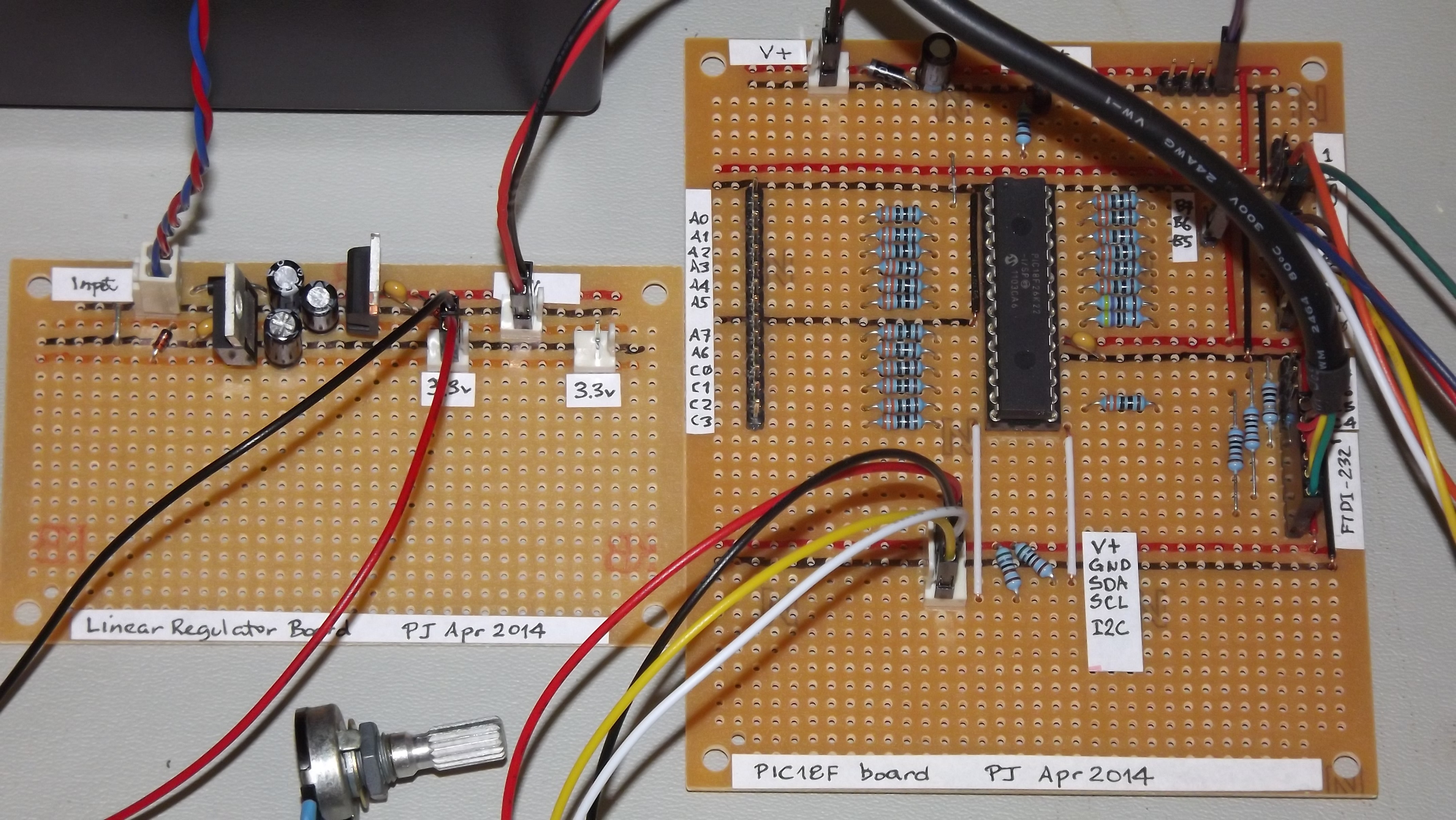
Here is a detailed view of the home-made demo board with PIC18F26K22 in place. This board is suitable for the exercises in this guide. A separate regulator board is to the left and a current-limited supply provides the input power. The board is simple to make by hand, with header pins for the reset switch and connections to the LEDs. The 4-pin header in the foreground provides an I2C connection. The ICSP header is only needed to program FlashForth into the MCU, initially. All communication with the host PC is then via the TTL-level serial header (labelled FTDI-232) at the right. Beyond the minimum required to get the microcontroller to function, we have current-limiting resistors and header pins on most of the MCU’s I/O pins. This arrangement is convenient for exercises such as interfacing to the 4x3 matrix keypad discussed in a later section.
The schematic diagram of this home-brew board is shown on the following page. Note that there is no crystal oscillator on the board; the internal oscillator is sufficiently accurate for asynchronous serial port communication. Note, also, the 1k resistors in the TX and RX nets. These limit the current going through the microcontroller pin-protection diodes in the situation where the microcontroller board is unpowered and the FTDI-232 cable is still plugged in to your PC. This will happen at some point and, without the current-limiting resistors, the FTDI cable will power the microcontroller, probably poorly.

2.2. AVR and PIC24 boards
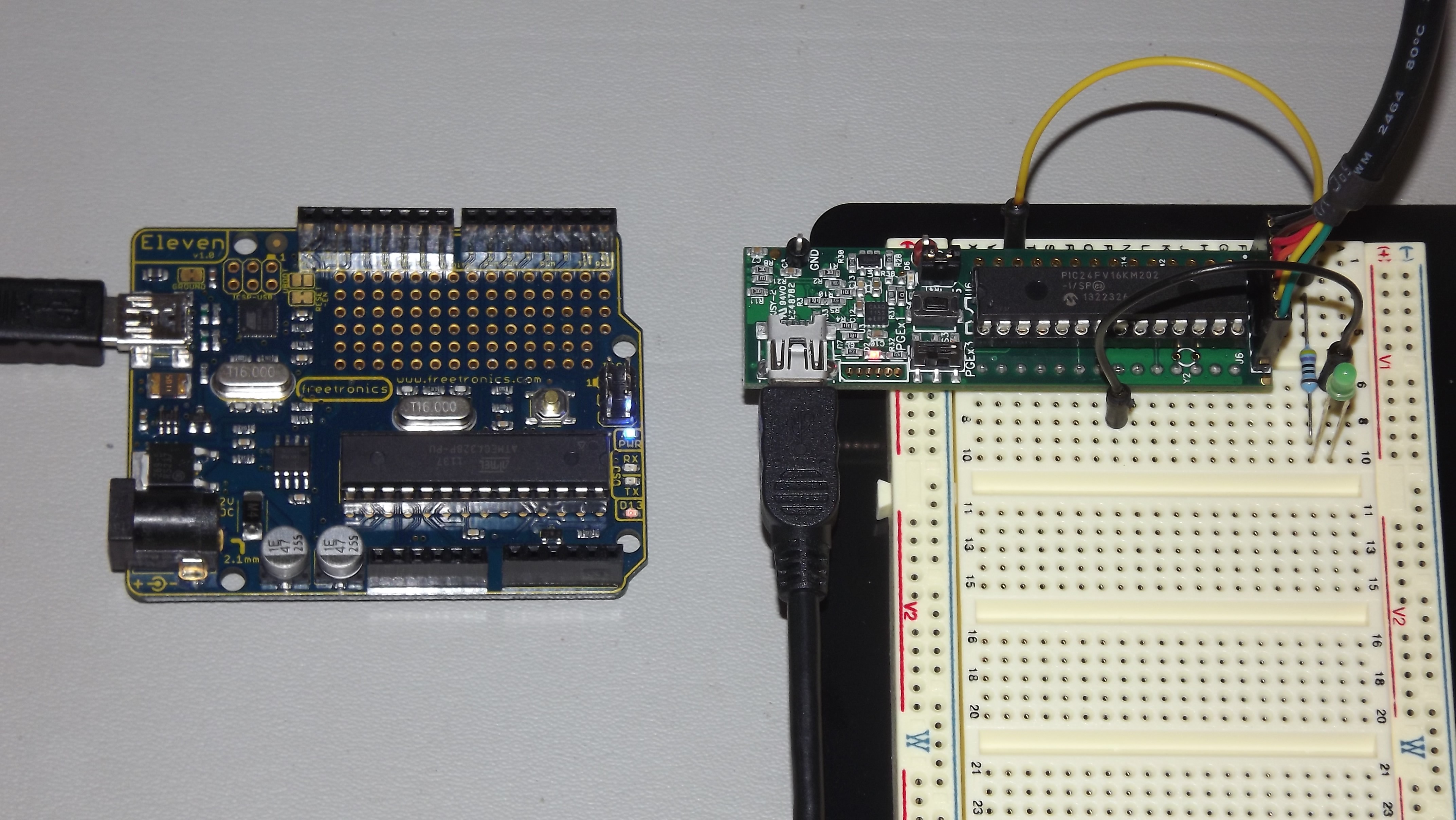
The Eleven from Freetronics, shown in the left half of the following photograph, is an Arduino-compatible board carrying an ATmega328P microcontroller. This is a convenient piece of hardware with many prototype-friendly boards available to plug into the headers around the periphery of the board. Although these boards come with the Arduino bootloader preprogrammed into the ATmega328 microcontroller, the standard AVR 6-pin programming header on the right-hand end of the board (in the photo) can be used to reprogram the microcontroller with the FlashForth interpreter. Power and serial port access is through the USB connector at the left.
If you want an almost-no-solder option for prototyping with the PIC24FV32KA302, Microchip provide the Microstick 5V for PIC24K-series. As shown in the following photograph, this is convenient in that it includes a programmer on-board and can be plugged into a bread-board. The power supply and flash programming access is provided through the USB connector on the left of the board while the serial port connection is via the 6-pin connector on the right-end of the board.
Building a minimal board, by hand, for any of these processors is fairly easy and strip-board versions for each is shown in the following photograph. The left-hand board is for the PIC18F26K22, before all of the extra protection resistors were added. In this state, FlashForth can already be used on this board for nearly all of the exercises in the following sections. Schematic diagrams for the PIC24 and AVR microcontrollers are shown on the following pages.
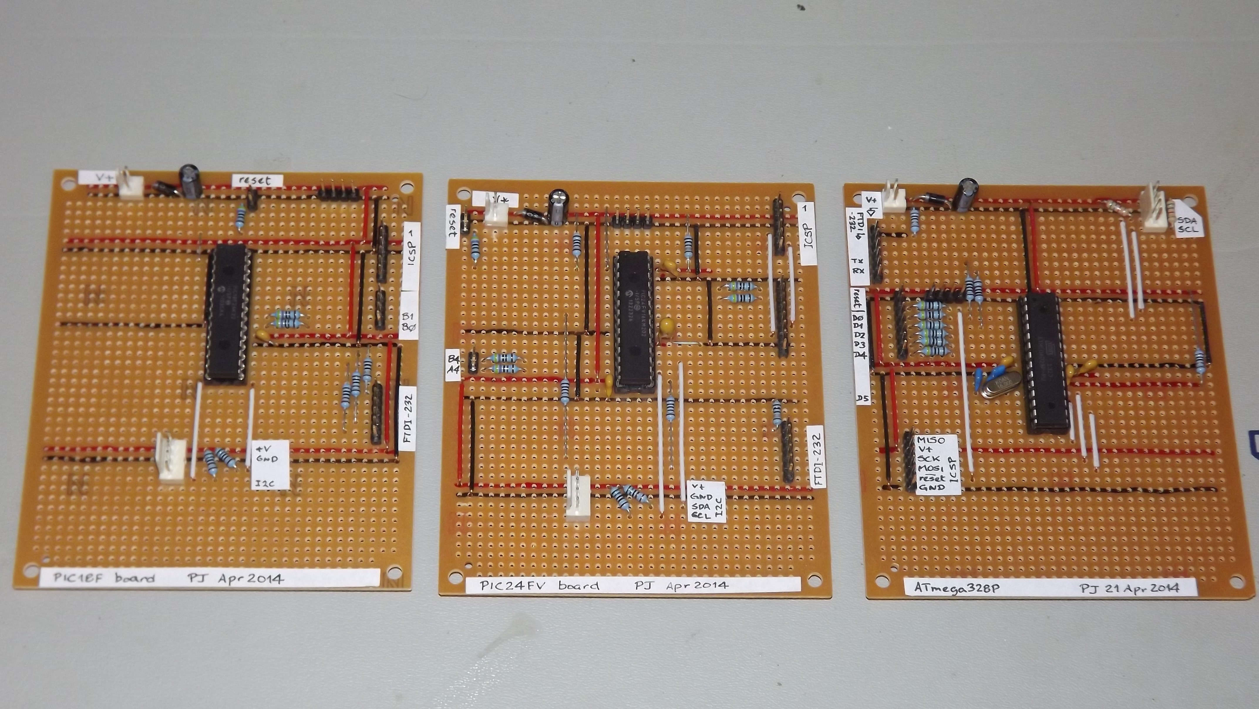
Each of the boards has headers for (1) power, (2) in-circuit serial programming, (3) I2C communication and (4) TTL-level-232 serial communication. The ATmega328 board on the right has a few more protection resistors installed and has an 16\,MHz crystal because serial-port communication was found to be unreliable using the internal oscillator.


3. FlashForth
Forth is a word-based language, in which the data stack is made available to the programmer for temporary storage and the passing of parameters to functions. Everything is either a number or a word. Numbers are pushed onto the stack and words invoke functions. The language is simple enough to parse that full, interactive Forth systems may be implemented with few (memory) resources. Forth systems may be implemented in a few kilobytes of program memory and a few hundred bytes of data memory such that it is feasible to provide the convenience of a fully interactive program development on very small microcontrollers.
The classic beginners book by Brodie1 is available online, as is Pelc’s more recent book3. A more detailed reference is published by Forth Inc2. These books are biased toward Forth running on a personal computer rather than on a microcontroller, however, they are a good place to start your reading. For an introductory document that is specific to FlashForth, see the companion document, Elements of FlashForth 5.
FlashForth for the PIC18, PIC24 and ATmega families of microcontrollers is a full interpreter and compiler that runs entirely on the microcontroller. It is a 16-bit Forth with a byte-addressable memory space. Even though there are distinct memory types (RAM, EEPROM and Flash) and separate busses for data and program memory in these Harvard-architecture microcontrollers, FlashForth unifies them into a single 64kB memory.
Above working in assembler, FlashForth does use some resources, both memory and compute cycles, but it provides such a nice, interactive environment that these costs are usually returned in convenience while tinkering with your hardware. Forth programs are very compact so you will have less code to maintain in the long run. The interpreter can also be available to the end user of your instrument, possibly for making parameter adjustments or for making the hardware versatile by having a collection of application functions present simultaneously in the firmware, with the user selecting the required function as they wish.
3.1. Getting FlashForth and programming the MCU
FlashForth is written in assembler, with one program source for each of the microcontroller families and a number of Forth text files to augment the core interpreter. The source code can be downloaded from SourceForge at the URL http://sourceforge.net/projects/flashforth/ There, you will see that you can get a packaged release or you can clone the git repository.
To build from this source, you will need to start up your integrated development environment (be it MPLAB, MPLAB-X or AVR Studio), open the program source and config files in this IDE and edit the config file(s) to match your selection of oscillator. There are other options to customize but the choice of oscillator is the main one. The machine code can then be assembled and programmed into your microcontroller with a suitable device programmer (PICkit3, ICD3, STK500, AVRISP MkII, …). Once programmed with FlashForth, and mounted in a board that provides power and serial communications as described in the previous section, you will be ready to interact with FlashForth via a serial terminal or shell.
3.2. Building for the PIC18F26K22 or PIC18F46K22
For our minimal system with either the PIC18F26K22 or PIC18F46K22 microcontroller, we elect to use the internal (16 MHz) oscillator multiplied by 4 by the PLL.
Within the MPLAB-X development environment,
we navigate to the pic18/src/ directory and open the project file FF.X
to build our variant of the FlashForth program.
At the time of writing these notes, the FF.X project file in the source directory had
been configured for a PIC18F25K50 microcontroller.
So, opening the project’s properties,
we select our specific device (PIC18F26K22), our hardware tool (ICD3),
and the compiler toolchain (pic-as).
To build the actual machine code that will be programmed into the flash memory
of the PIC18F26K22,
it is sufficient to assemble the principal source file ff-pic18.S
along with the configuration files
p18f-main.inc, p18fxxxx.inc, p18f2x4xk22.inc.
The source file and config files can be found in the directory pic18/src/.
There may be other configuration files already added to the project but you can ignore them.
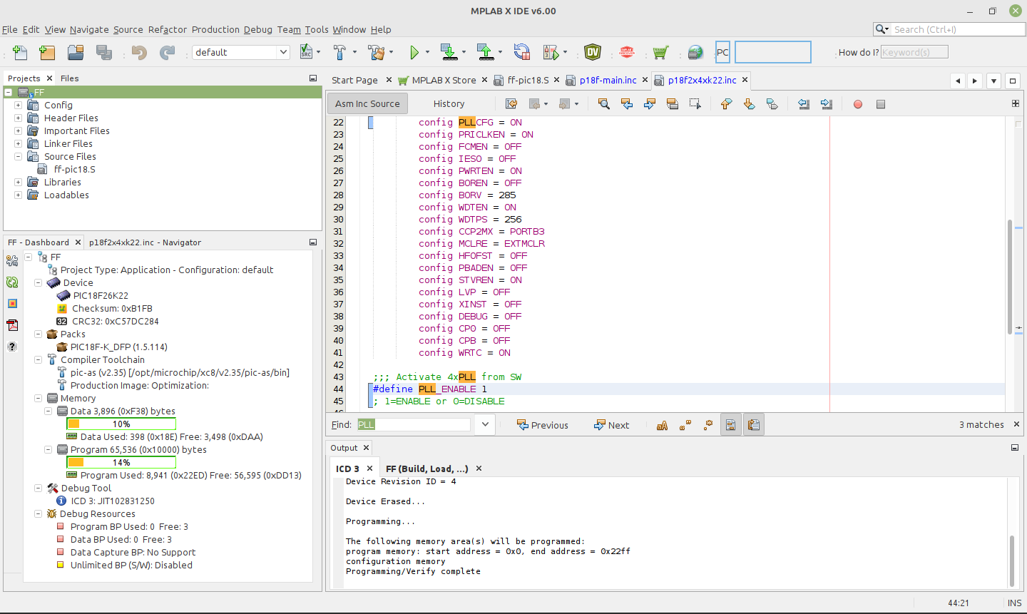
As shown in the MPLAB-X image below,
we edit the PIC18F26K22-processor-specific config file, p18f2x4xk22.inc,
writing PLLCFG = ON to have the PLL enabled (giving FOSC = 64 MHz).
Also, toward the bottom of the file we define PLL_ENABLE as 1.
To see your options for all of the configuration bits for your specific microcontroller,
it is convenient to open the MPLAB-X view from the main menu:
Window → Target Memory Views → Configuration Bits.
We also enable the watchdog timer with a 1:256 postscale (WDTPS = 256)
to get approximately a 1 second time-out period,
and enable the external reset capability (MCLRE = EXTMCLR).
Being able to reset the microcontroller by bringing the MCLR pin low is something that
we find convenient when tinkering with new hardware.
Having enabled the PLL, we need to edit the p18f-main.inc file
to set the system clock frequency as clock equ 64000000 // Hz.
With this clock frequency, the microcontroller requires approximately 7 mA current while
the interpreter is running and waiting for input.
We also enable the reception of a Control-O character as a warm reset with the line
#define CTRL_O_WARM_RESET ENABLE
There are many other options for customizing the FlashForth program in this file, however, the default parameters are fine for the first build of our minimal system.
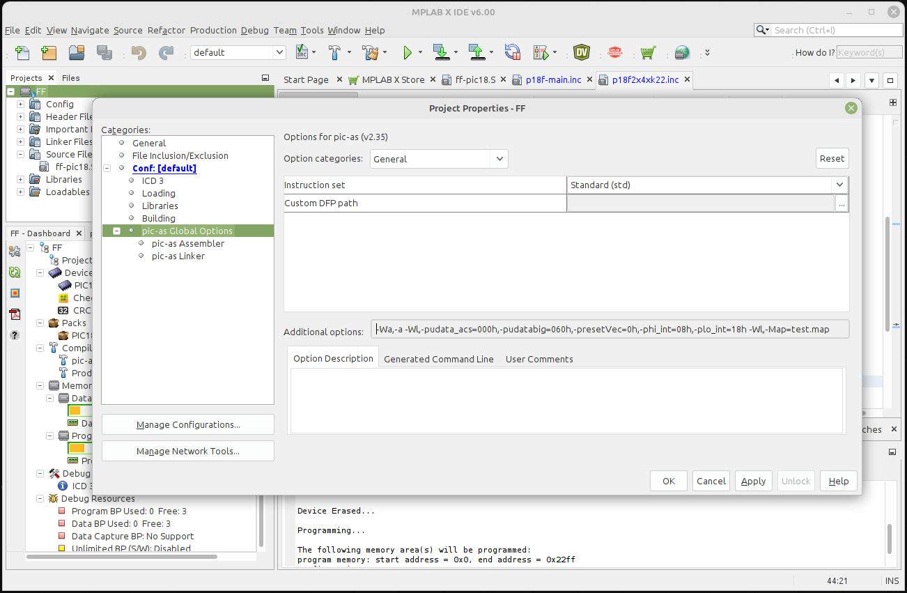
Before we build, we need to specify the placement of the code and data
as options to the linker.
This can be done via the Additional options text entry for the pic-as assembler,
as shown in the following screen shot.
Suitable values for these options have been provided by Mike Nordman,
as a comment near the top of the p18f2x4xk22.inc configuration file.
The final step is to program the FlashForth machine code into the flash memory of the microcontroller, using whatever device programmer you happen to have plugged into your development system. We have seleted to use of an MPLAB ICD3.
The first of the two MPLAB-X images above shows the result of building and downloading the code to the microcontroller. The lower left frame in the MPLAB-X window shows the MCU resources used. With 398 bytes of SRAM used (another 3498 free) and 8941 bytes of program memory used (56595 free), For the PIC18F26K22 MCU, FlashForth occupies only about one-seventh of the microcontroller’s program memory. Most of the memory is available for your application. For more details on the SRAM memory map, see the FlashForth 5 Quick Reference. There, Mikael Nordman has provided a memory map that shows how the SRAM memory is allocated within the FlashForth system.
3.3. Building for the PIC24FV32KA302
Building for the 16-bit PIC24 family is similar process.
This time look for the source code files in the pic24/src/ subdirectory.
For our PIC24FV32KA302-I/SP microcontroller
using its internal 8 MHz oscillator with 4X PLL
and installed on the home-made minimal board,
the configuration files have suitable settings already.
A new stand-alone MPLAB-X project was started and the following files added:
-
the main source file
ff-pic24-30-33.s, -
configs.cto set the configuration bits via pragma statements, -
ff24.incto set the memory sizes for the selected microcontroller, -
p24fk_config.incto setFREQ_OSCwith yourFNOSCselection inconfigs.cand to select the operator UART. -
registers.incto define some regiaters in the Flashforth core dictionary.
Flashforth uses 542 of the microcontroller’s 2048 bytes of SRAM and 4271 of the MCU’s 11 kwords of Flash memory. This leaves most of the memory for your Forth application program. Although this appears to be a lot less than that available in the PIC18F26K22 MCU, this 16-bit MCU has lots of interesting hardware. With instruction cycle frequency of 16 MHz and the interpreter waiting for input, the current consumption is 7.5 mA, approximately the same as for the 8-bit PIC18F26K22.
3.4. Installing on an ATmega328P
Mike Nordman has made life even simpler for users of Arduino-like hardware by providing
a number of prebuilt .hex files that can be programmed into your AVR microcontroller.
For the ATmega328P with a 16 MHz crystal,
we chose to program the avr/hex/328-16MHz-38400.hex file.
Here is the command for programming that file using avrdude on a Linux computer
where an AVR ISP MkII programmer appears as the serial port /dev/ttyUSB1.
$ sudo avrdude -p m328p -B 8.0 -c avrisp2 -P /dev/ttyUSB1 -e \
  -U efuse:w:0xff:m \
  -U hfuse:w:0xdf:m \
  -U lfuse:w:0xff:m \
  -U flash:w:328-16MHz-38400.hex:i
4. Interacting with FlashForth
Principally, interaction with the programmed MCU is via the serial port. For the PIC microcontrollers, settings are 38400 baud 8-bit, no parity, 1 stop bit, with software (Xon/Xoff) flow control. For the ATmega328P (as programmed above), the baud rate is 9600.
The FlashForth distribution includes a couple of shell programs that are
programmed with some knowledge of the FlashForth interpreter.
The ff-shell.py program is written in Python and allows interaction
with the microcontroller via a standard command shell.
It depends on a Python interpreter and the pyserial extension being installed on your PC.
The ff-shell.tcl is a GUI program that displays the interaction text in a dedicated window on your PC.
It requires the Tcl/Tk interpreter which is usually part of a Linux environment but it may be
installed on MS-Windows or MacOS as well.
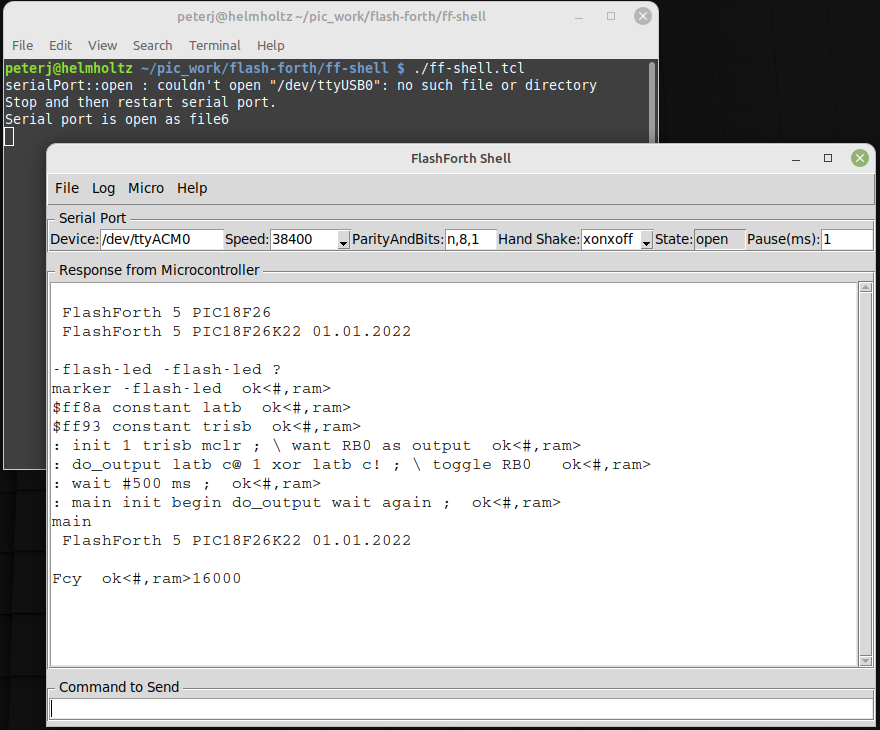
The following images shows the ff-shell.tcl window just after sending the content
of the flash-led-pic18.txt file to the PIC18F26K22.
The device name of /dev/ttyACM0 on the status line refers to the USB-to-serial interface
that was plugged one of the PC’s USB ports.
It is convenient to start the program with the command
$ sudo ./ff-shell.tcl
Use the sudo prefix only if you do not have sufficient permissions
to access the USB hardware on your system.
If necessary, you can adjust the communication settings
by typing new values into the entry boxes
and pressing Enter to repoen the connection.

As you type characters into the main text widget, ff-shell.tcl intercepts them and sends them,
one at a time, via the serial port to the microcontroller.
As the microcontroller sends characters back, the program filters them and displays them in the text widget.
There is also a send-file capability that will send the text from the file
as fast as it can, without overwhelming the microcontroller.
The Python program ff-shell.py has a special command #send to start the equivalent process.
If you have sent the microcontroller off to do a repetitive task, such as flashing the LED indefinitely,
you can regain the interpreter’s attention by sending a Control-O character.
The interpreter aborts the execution of the current word and does a software restart.
After initialization, the interpreter announces that it is ready to begin.
The warm restart action is also available from the menu as Micro → Warm Restart.
Subsequently typing the name of another word and pressing Enter will get a response.
As shown below,
the Fcy word will leave the instruction-cycle frequency (in kHz) on the stack.
We find ff-shell.tcl a very convenient interaction environment, however,
if you want to use a standard terminal program on Linux, MS-Windows or MacOS,
there are a number of good options.
5. Introductory examples
We begin with examples that demonstrate a small number of features of the MCU or of FlashForth. Our interest will primarily be in driving the various peripherals of the MCU rather than doing arithmetic or dealing with abstract data.
5.1. Flash a light-emitting diode with the PIC18
The microcontroller version of the "Hello, World" program is typically a program that flashes a single LED. It will work on either of PIC18F microcontrollers mentioned previously and makes use of a digital input-output pin via the registers that control the IO port. The manufacturer’s datasheet has a very readable introduction to the IO ports. Please read it.
-flash-led
marker -flash-led
$ff8a constant latb
$ff93 constant trisb
: init 1 trisb mclr ; \ want RB0 as output
: do_output latb c@ 1 xor latb c! ; \ toggle RB0
: wait #500 ms ;
: main init begin do_output wait again ;
main
Notes on this program:
-
If the word
-flash-ledhas been previously defined with the word marker, line 1 resets the dictionary state and continues interpreting the file, else the interpreter signals that it can’t find the word and continues interpreting the file anyway. -
Line 2 records the state of the dictionary and defines the word
-flash-ledso that we can reset the dictionary to its state before the code was compiled, simply by executing the word \verb!-flash-led!. -
Lines 3 and 4 define convenient names for the addresses of the special function registers (SFRs) that control IO-port B. Note the literal hexadecimal notation with the
$character. In the PIC18F family, the SFRs appear near the top of the 64k FlashForth memory space. -
Line 5 is a colon definition for the word \verb!init! that sets up the peripheral hardware. Here, we set pin RB0 as output. The actual command that does the setting is
mclr, which takes a bit-mask (00000001) and a register address ($ff93) and then clears the register’s bits that have been set in the mask. Note the comment starting with the backslash character. Although the comment text is sent to the MCU, it is ignored. Note, also, the spaces delimiting words. That spaces after the colon and around the semicolon are important. -
Line 6 is the definition that does the work of fiddling the LED pin. We fetch the byte from the port B latch, toggle bit 0 and store the resulting byte back into the port B latch.
-
Line 7 defines a word to pause for 500 milliseconds. Note the
#character for a literal decimal integer. -
Line 8 defines the "top-level" coordination word, which we have named
main, following the C-programming convention. After initializing the relevant hardware, it unconditionally loops, doing the output operation and waiting, each pass. -
Line 9 invokes the
mainword and runs the application. Pressing theResetbutton will trigger a hardware restart, kill the application and put the MCU back into a state of listening to the serial port. Invoking a warm restart by typingControl-Oor selecting theWarm Restartmenu action inff-shell.tclmay be a more convenient way to stop the application. Typingmain, followed byEnterwill restart the application.
Instead of going to the bother of tinkering with the MCU IO Port, we could have taken a short-cut and used the string writing capability of Forth to write a short version that was closer the the operation of typical Hello World programs.
: greet-me ." Hello World" ;
greet-me
Before going on to more examples, it is good to know about the word empty.
This word will reset the dictionary and all of the allotted-memory pointers.
Because FlashForth does not allow you to redefine words that are already in the dictionary,
later examples that use the same names for their word definitions,
may not compile without complaint if you don’t clean up after each exercise.
5.2. Flash a light-emitting diode with the PIC24
-flash-led
marker -flash-led
$02c8 constant trisb
$02cc constant latb
1 #15 lshift constant bit15
: init bit15 trisb mclr ; \ set pin as output
: do_output latb @ bit15 xor latb ! ; \ toggle the bit
: main init begin do_output #500 ms again ;
main
Notes on this program:
-
This program for the 16-bit microcontroller is essentially the same as that for the 8-bit MCU, with different addresses for the port-control registers, of course. In the PIC24/dsPIC30/dsPIC33 version of FlashForth, the special function registers appear in the lowest 2k bytes of memory.
-
On line 5, we compute the bit pattern for selecting the MCU pin rather than writing it explicitly. We start with a 1 in the least-significant bit of the 16-bit word and then shift it left 15 places, to produce the binary value
%1000000000000000 -
On line 7, we use 16-bit fetch
@and store!operations because the special function registers for controlling the hardware on this microcontroller are 16 bits wide.
5.3. Flash a light-emitting diode with the ATmega
-flash-led-avr
marker -flash-led-avr
\ PB5 is Arduino digital pin 13.
\ There is a LED attached to this pin on the Freetronics Eleven.

$0024 constant ddrb
$0025 constant portb
1 #5 lshift constant bit5

: init bit5 ddrb mset ; \ set pin as output
: do_output portb c@ bit5 xor portb c! ; \ toggle the bit
: main init begin do_output #500 ms again ;

main
Notes on this program:
-
Again, except for the specific registers and bits, this program is the same as for the other MCUs. As for other high-level languages, we no longer have to think about the specific machine architecture (usually).
-
Because we are using load and store instructions, the special function registers start at address
$20.
5.4. Set the cycle duration with a variable (PIC18)
We enhance the initial demonstration by making the waiting period setable. Because of the interactive FlashForth environment, the extra programming effort required is tiny. The appearance of the code, however, looks a bit different because we have laid out the colon definitions in a different style and have included more comments.
-flash-led-var
marker -flash-led-var
\ Flash a LED attached to pin RB0.

$ff8a constant latb
$ff93 constant trisb
variable ms_count \ use this for setting wait period.

: init ( -- )
  1 trisb mclr  \ want RB0 as output
;

: do_output ( -- )
  latb c@ 1 xor latb c!  \ toggle RB0
;

: wait ( -- )
  ms_count @ ms
;

: main ( n -- )
  ms_count !  \ store for later use in wait
  init
  begin
    do_output
    wait
  again
;

#500 main  \ exercise the application
Notes on this program:
-
If the file has been sent earlier defining the application’s words, line 1 resets the state of the dictionary to forget those previous definitions. This makes it fairly convenient to have the source code open in an editing window (say, using
emacs) and to simply reprogram the MCU by resending the file (with theSend-Filemenu item inff-shell.tcl). -
Line 7 defines a 16-bit variable
ms_count. -
Line 30 leaves the wait period on the stack before invoking the
mainword. -
On each pass through the
waitword, the 16-bit value is fetched from -
ms_countand is used to determine the duration of the pause.
5.5. Hello, World: Morse code
Staying with the minimal hardware of just a single LED attached to pin RB0 on the PIC18F26K22 or PIC18F46K22, we can make a proper "Hello World" application. The following program makes use of Forth’s colon definitions so that we can spell the message directly in source code and have the MCU communicate that message in Morse code.
-hello-world
marker -hello-world
\ Flash a LED attached to pin RB0, sending a message in Morse-code.

$ff8a constant latb
$ff93 constant trisb
variable ms_count \ determines the timing.

: init ( -- )
  1 trisb mclr  \ want RB0 as output
  1 latb mclr   \ initial state is off
;

: led_on 1 latb mset ;
: led_off 1 latb mclr ;
: gap ms_count @ ms ; \ pause period
: gap2 gap gap ;
: dit led_on gap led_off gap2 ;
: dah led_on gap2 led_off gap2 ;

\ Have looked up the ARRL CW list for the following letters.
: H dit dit dit dit ;
: e dit ;
: l dit dit ;
: o dah dah dah ;
: W dit dah dah ;
: r dit dah dit ;
: d dah dit dit ;

: greet ( -- )
  H e l l o  gap  W o r l d  gap2
;

: main ( n -- )
  ms_count !  \ store for later use in gap
  init
  begin
    greet
  again
;

#100 main  \ exercise the application
6. Read and report an analog voltage
6.1. PIC18FX6K22
Use of the analog-to-digital converter (ADC) is a matter of, first, reading Section 17 of the PIC18F2X/4XK22 datasheet, setting the relevant configuration/control registers and then giving it a poke when we want a measurement. Again, the interactive nature of FlashForth makes the reporting of the measured data almost trivial.
-read-adc
marker -read-adc
\ Read and report the analog value on RA0/AN0.

\ Registers of interest on the PIC18F26K22
$ffc4 constant adresh
$ffc3 constant adresl
$ffc2 constant adcon0
$ffc1 constant adcon1
$ffc0 constant adcon2
$ff92 constant trisa
$ff38 constant ansela

: init ( -- )
  1 trisa mset \ want RA0 as input
  1 ansela mset
  %00000000 adcon1 c! \ ADC references Vdd, Vss
  %10101111 adcon2 c! \ right-justified, 12-TAD acq-time, FRC
  %00000001 adcon0 c! \ Power on ADC, looking at AN0
;

: adc@ ( -- u )
  %10 adcon0 mset \ Start conversion
  begin %10 adcon0 mtst 0= until \ Wait until DONE
  adresl @
;

: wait ( -- )
  #500 ms
;

: main ( -- )
  init
  begin
    adc@ u.
    wait
  key? until
;

\ Exercise the application, writing digitized values periodically
\ until any key is pressed.
decimal
main
Notes on this program:
-
Although not much needs to be done to set up the ADC, you really should read the ADC section of the datasheet to get the full details of this configuration.
-
Lines 17 to 19 uses binary literals (with the
%character) to show the configuration bits explicitly. -
Line 24 conditionally repeats testing of the DONE bit for the ADC.
-
Line 25 fetches the full 10-bit result and leaves it on the stack for use after the
adc@word has finished. Because of the selected configuration of the ADC peripheral, the value will be right-justified in the 16-bit cell. -
Line 35 invokes the
adc@word and prints the numeric result. -
Line 37 checks if a character has come in from the serial terminal. If so, the loop is terminated and the main function returns control to the FlashForth interpreter.
6.2. PIC24FV32KA30X
The analog-to-digital converter on the PIC24-series microcontrollers is a little more complex than that on the PIC18 series. There are more features to select and so there are more registers and bits to set, however, the essential set-up tasks are similar. The following script sets up some word definitions that were developed with a view to using them in a larger program. The particular words are more verbose but also carry more information.
-read-adc
marker -read-adc
\ Read and report the analog values on AN0 through AN3.

\ Registers of interest on the PIC24FV32KA30x
$0084 constant ifs0

$02c0 constant trisa
$02c2 constant porta
$02c4 constant lata
$02c6 constant odca

$02c8 constant trisb
$02ca constant portb
$02cc constant latb
$02ce constant odcb

$0300 constant adc1buf0
$0340 constant ad1con1
$0342 constant ad1con2
$0344 constant ad1con3
$0348 constant ad1chs

$04e0 constant ansa
$04e2 constant ansb

$0770 constant pmd1

\ bit masks
$0001 constant mADC1MD \ pmd1
$0001 constant mDONE \ ad1con1
$0002 constant mSAMP
$8000 constant mADON
$2000 constant mAD1IF


: adc.init ( -- )
  $0003 trisa mset \ want RA0, RA1 as input
  $0003 ansa mset
  $0003 trisb mset
  $0003 ansb mset
  mADC1MD pmd1 mclr \ ensure module enabled
  $0470 ad1con1 ! \ 12-bit, auto-convert
  $0000 ad1con2 ! \ ADC references Vdd, Vss
  $9f00 ad1con3 ! \ ADRC, 31-TAD acq-time
  $0000 ad1chs ! \ neg input is Vss, pos input AN0
  mADON ad1con1 mset \ Power on ADC
  mAD1IF ifs0 mclr
;

: adc.close ( -- )
  mADON ad1con1 mclr
  mAD1IF ifs0 mclr
;

: adc.select ( u -- ) \ select positive input
  $0003 and ad1chs ! \ limit selection to AN0 through AN3
;

: adc@ ( -- u )
  mDONE ad1con1 mclr
  mSAMP ad1con1 mset \ Start sampling
  begin mDONE ad1con1 mtst until \ Wait until done.
  adc1buf0 @
;

: adc@.filter ( -- u )
  0 \ start of sum
  8 for adc@ + next
  8 /
;

: wait ( -- )
  #500 ms
;

: adc.test ( -- )
  adc.init
  begin
    0 adc.select adc@.filter u.
    1 adc.select adc@.filter u.
    cr
    wait
  key? until
  adc.close
;

\ Exercise the application, writing digitized values periodically
\ until any key is pressed.
\ decimal
\ adc.test
Notes on this program:
-
This script was part of a larger application for the monitoring of 2 pressure transducers, hence the setting up of just RA0 and RA1 at the start of
adc.initat lines 38—41. -
To save power the peripheral modules of a PIC24 are, by default, disabled. You need to clear a module’s disable bit (line 42) to do anything with it, even setting configuration registers. The (separate) power-on bit still needs to be set to start up the converter.
6.3. ATmega328P
Although the analog-to-digital converter on the ATmega328P is different in detail,
it has essentially the same functionality that can be abstracted.
To control the ADC module, we can set up the same words
(adc.init, adc.close, adc.select and adc@)
as for the PIC24FV32KA302.
-read-adc
marker -read-adc
\ Read and report analog voltages

\ Registers of interest on the ATmega328P
$78 constant adcl
$79 constant adch
$7a constant adcsra
$7b constant adcsrb
$7c constant admux
$7e constant didr0

\ Bit masks
%10000000 constant mADEN
%01000000 constant mADSC
%00010000 constant mADIF

: adc.clear.iflag ( -- )
  mADIF adcsra mset \ clear by writing 1
;

: adc.init ( -- )
  $3f didr0 c! \ Disable digital inputs 5 through 0
  $40 admux c! \ AVcc as ref, right-adjust result, channel 0
  $06 adcsra c! \ single conversion mode, prescaler 64
  mADEN adcsra mset \ enable ADC
  adc.clear.iflag
;

: adc.close ( -- )
  mADEN adcsra mclr
  adc.clear.iflag
;

: adc.wait ( -- )
  begin mADSC adcsra mtst 0= until
;

: adc.select ( u -- )
  adc.wait
  $0f and \ channel selected by lower nibble
  admux c@ $f0 and \ fetch upper nibble
  or admux c!
;

: adc@ ( -- u )
  adc.wait
  mADSC adcsra mset
  adc.wait
  adcl c@ adch c@ #8 lshift or
  adc.clear.iflag
;

: adc.test ( -- ) \ Exercise the analog converter
  adc.init
  begin
    0 adc.select adc@ ." adc0 " u.
    1 adc.select adc@ ." adc1 " u.
    cr
    #500 ms
  key? until
  adc.close
;

\ Now, start up the application...
\ decimal
\ adc.test
Notes on this program:
-
Although there are 6 analog pins available, the test word only exercises channels 0 and 1.
-
The input channel selection is controlled by the lower bits in the
admuxregister. Other than the 6 external analog input pins, you can select:-
the temperature sensor with bit pattern
%1000, -
the internal band-gap reference with
%1110, and -
and the zero-volt rail (GND) with
%1111.
-
7. Counting button presses
Example of sensing a button press, with debounce in software.
\ Use a push-button on RB0 to get user input.
\ This button is labelled S3 on the PICDEM2+ board.
-pb-demo
marker -pb-demo

$ff81 constant portb
$ff8a constant latb
$ff93 constant trisb

variable count

: init ( -- )
  %01 trisb mset \ RB0 as input
  %10 trisb mclr \ RB1 as output
  %10 latb mclr
;
: RB1toggle ( -- )
  latb c@ %10 xor latb c!
;
: RB0@ ( -- c )
  portb c@ %01 and
;
: button? ( -- f )
  \ Check for button press, with software debounce.
  \ With the pull-up in place, a button press will give 0.
  RB0@ if
    0
  else
    #10 ms
    RB0@ if 0 else -1 then
  then
;

: main ( -- )
  0 count !
  init
  begin
    button? if
      RB1toggle
      count @ 1+ count !
      count @ .
      #200 ms \ allow time to release button
    then
    cwd
  key? until
;

main  \ exercise the application
Notes on this program:
-
The
mainword clears thecountvariable, callsinitto set up the hardware and then loops, pollingRB0and incrementing value of thecountvariable only when the button gets pressed. -
If the pause after acknowledging the button press (line 42) is too long, we may lose later button press events. This depends on how frantically we press S3.
-
Line 44 resets the watch-dog timer on each pass of the main loop. If we don’t press the RB0 button for a long time, the main loop would not otherwise pause and clear the watch-dog timer. The watch-dog timer is cleared inside the
msword, however, if the timer expires before being cleared, the microcontroller would be reset and the FlashForth interpreter would restart.
8. Counting button presses via interrupts
Instead of polling the RB0 pin attached to the push button, as in the previous example, let’s set up the hardware interrupt mechanism to invoke the increment action for us.
\ Use a push-button on RB0 to get user input, via an interrupt.
\ This button is labelled S3 on the PICDEM2+ board.
\ Don't have J6 connected because the LED on RB0 loads the pull-up.

-pb-interrupt
marker -pb-interrupt

$ff93 constant trisb
$fff2 constant intcon
$fff1 constant intcon2

variable count
variable last-count

: int0-irq
  [i
    %10 intcon mtst \ INT0IF
    if
      count @ 1+ count !
      %10 intcon mclr
    then
  i]
;i

: init ( -- )
  %01 trisb mset \ RB0 as input, a button press will give 0.
  %01000000 intcon2 mclr \ interrupt on falling edge
  ['] int0-irq 0 int! \ install service word
  %10 intcon mclr \ INT0IF cleared
  %10000 intcon mset \ INT0 interrupt enable
;

: main ( -- )
  0 count !
  init
  begin
    count @ last-count @ - \ change?
    if
      count @ dup last-count ! .
    then
    cwd
  key? until
;

main  \ exercise the application
Notes on this program:
-
Again, we use the variable named
countas the variable to be incremented on pressing the button that pulls RB0 low. The actual increment is done on line 19, inside the interrupt service wordint0-irq. The second variable,last-count, is used on line 36 in themainword, to detect when thecountvariable changes. -
The
initword sets up the bits to enable theINT0external interrupt to fire on a falling edge at RB0. -
On line 28 in the
initword, the execution token for our interrupt service word is stored as the high-priority interrupt vector. Because FlashForth supports only high-priority interrupts, the0is a dummy value but is still expected by theint!word. -
Inside the interrupt-service word, we need to test the
INT0IFinterrupt flag to see if it is our interrupt to handle and, if it is, do the appropriate work (of incrementing thecountvariable) and clearing the interrupt flag. If you enable several interrupt sources, you need to provide a test and action for each. -
The
mainword clears thecountvariable, callsinitto set up the interrupt mechanism and then loops, emitting the value of thecountvariable only when it changes.
9. Scanning a 4x3 matrix keypad
We connect a 4x3 matrix keypad to PORTB, using RB0, RB1 and RB2 to drive the columns while sensing the rows with RB4 through RB7. The schematic figure below shows the arrangement of keys and pins.

To minimize hardware, we have used the weak pull-ups on PORTB. Pressing a key while its column wire is held high does nothing, however, pressing a key on a column that is held low will result in its row being pulled low.
-keypad
marker -keypad
\ Display key presses from a 4x3 (telephone-like) keypad
\ on PIC18F26K22-I/SP

$ff81 constant portb
$ff8a constant latb
$ff93 constant trisb
$ff39 constant anselb
$ff61 constant wpub
$fff1 constant intcon2

: init ( -- )
  0 latb c!
  %00000000 anselb c!    \ set as all digital I/O pins
  %11110000 trisb c!     \ RB7-4 as input, RB3-0 as output
  %11110000 wpub c!      \ pull-ups on RB7-4
  %10000000 intcon2 mclr \ turn on pull-ups
;

flash
create key_chars
  char 1 c, char 2 c, char 3 c,
  char 4 c, char 5 c, char 6 c,
  char 7 c, char 8 c, char 9 c,
  char * c, char 0 c, char # c,
create key_scan_bytes
  $7e c, $7d c, $7b c,
  $be c, $bd c, $bb c,
  $de c, $dd c, $db c,
  $ee c, $ed c, $eb c,
ram

: scan_keys ( -- c )
  \ Return ASCII code of key that is pressed
  #12 for
    key_scan_bytes r@ + c@
    dup
    latb c!
    portb c@
    = if
      \ key must be pressed to get a match
      key_chars r@ + c@
      rdrop
      exit
    then
  next
  0  \ no key was pressed
;

: keypad@ ( -- c )
  \ Read keypad with simple debounce.
  \ ASCII code is left on stack.
  \ Zero is returned for no key pressed or inconsistent scans.
  scan_keys dup
  #20 ms
  scan_keys
  = if exit else drop then
  0 \ inconsistent scan results
;

: main ( -- )
  init
  begin
    keypad@
    dup
    0= if
      drop  \ no key pressed
    else
      emit
      #300 ms \ don't repeat key too quickly
    then
  key? until
;
Notes on this program:
-
In lines 21—31, we make use of character arrays to store (into the program memory) the the ASCII code and the scan code for each key. The scan code is made up of the 3-bit column pattern to be applied to RB2-RB0 and the resulting 4-bit row-sense pattern (RB7-RB4) expected for the particular key if it is pressed. RB3 is maintained high (and is of no consequence) for this 3-column keypad, however, it would be used for a 4x4 keypad.
-
Lines 36 and 47 make use of the for—next control construct to work through the set of 12 scan codes.
-
We should go further by making use a state-machine and also keeping track of the last key pressed.
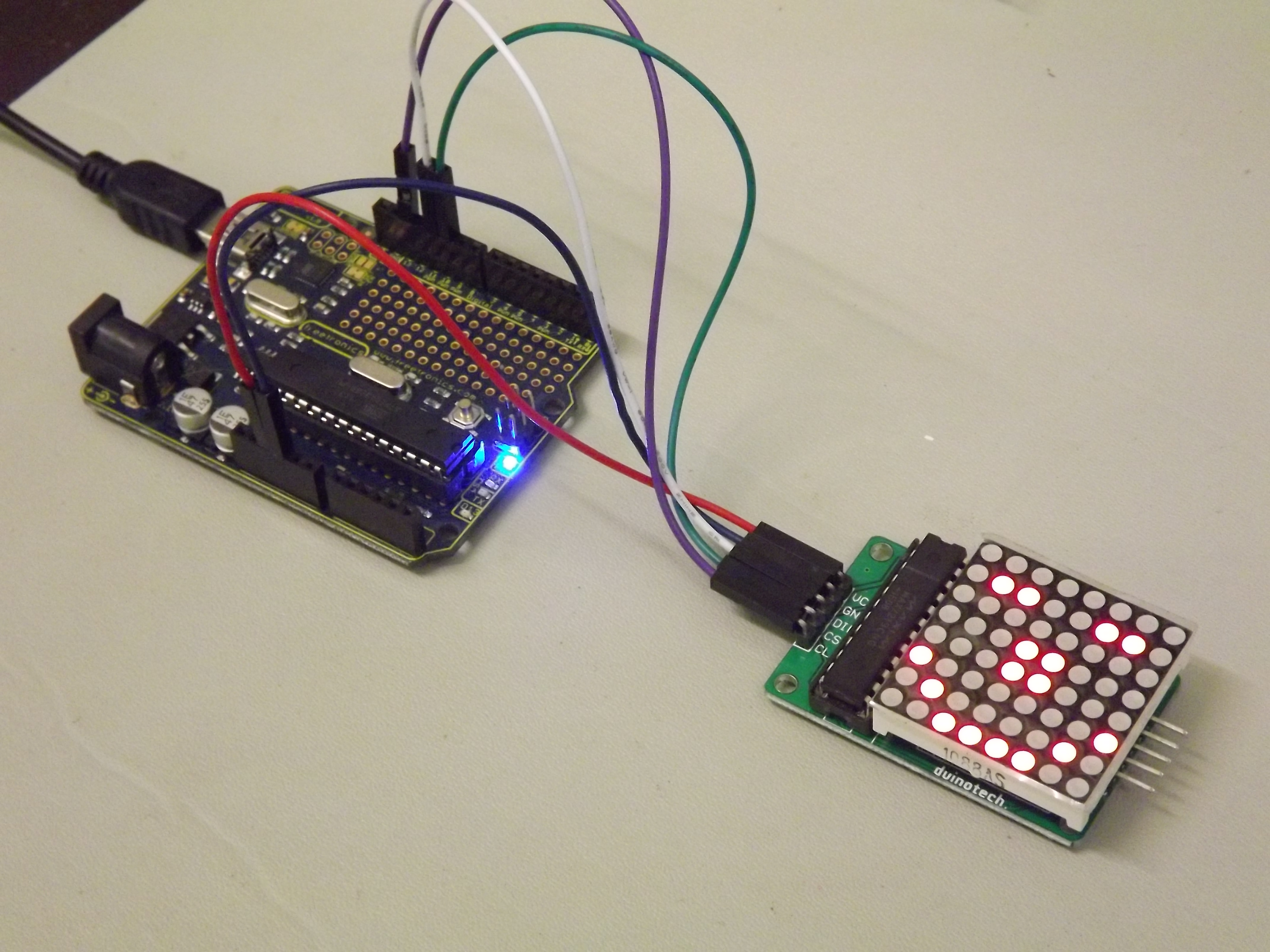
10. Communicating with SPI devices
The photograph below shows the Eleven AVR board driving a matrix display. This particular display board has an 8-by-8 LED matrix being controlled by a MAX7219 8-digit LED display driver.
The MAX7219 has a serial data interface that can be driven by the SPI module within each of the microcontrollers. The timing diagram, taken directly from the MAXIM datasheet, is shown below, along with the expect format for each 16-bit command. A command can be sent to the MAX7219 chip by taking the chip-select line low, sending two bytes via the SPI module and then taking the chip-select line high. A set of words for doing this 2-byte transfer and building the higher-level commands on top of that transfer is given after.

The following sections define the words for using SPI peripherals for each of the microcontrollers in master mode. The SPI module is initialized for mode 0 operation, with clock signal idling low, and data lines changing as the clock signal transitions from active to idle. This suits the MAX7219, which samples the data as the clock signal transitions from idle to active. These words provide abstract the hardware registers and bits to provide a common vocabulary for the interaction with SPI slave devices.
10.1. PIC18FX6K22
\ spi2-base-k22.txt
\ Words to drive the SPI2 module on the PIC18F26K22
\ PJ 31-Jan-2016
-spi2-base
marker -spi2-base

\ Registers of interest for MSSP2
$ff39 constant anselb
$ff61 constant wpub
$ff69 constant ssp2con3
$ff6c constant ssp2con1
$ff6d constant ssp2stat
$ff6e constant ssp2add
$ff6f constant ssp2buf
$ff81 constant portb
$ff8a constant latb
$ff93 constant trisb
$ffa4 constant pir3
$fff1 constant intcon2

\ bit masks
%0001 constant mSS2 ( RB0 )
%0010 constant mSCK2 ( RB1 )
%0100 constant mSDI2 ( RB2 )
%1000 constant mSDO2 ( RB3 )
$80 constant mRBPU
$80 constant mSSP2IF
$20 constant mSSP2EN

\ !SS2 is on RB0
: spi.select ( -- ) mSS2 latb mclr ;
: spi.deselect ( -- ) mSS2 latb mset ;

: spi.init ( -- ) \ set up SPI2 as master
  $0f anselb mclr \ enable digital for RB3 through RB0
  mSCK2 trisb mclr \ SCK as output
  mSCK2 latb mclr \ clock idles low
  mSDO2 trisb mclr \ MOSI as output
  mSDI2 trisb mset \ MISO as input
  $04 wpub c! \ activate pull-up on MISO (RB2) only
  mRBPU intcon2 mclr \ enable pull-ups
  mSS2 trisb mclr \ SS2 as output
  mSS2 latb mset \ deselect
  %01000000 ssp2stat c! \ SMP=0 CKE=1
  %00100010 ssp2con1 c! \ enable, CKP=0, Fosc/64
  mSSP2IF pir3 mclr
  ssp2buf c@ drop \ will clear BF
;
: spi.close ( -- )
  mSSP2EN ssp2con1 mclr
  mSSP2IF pir3 mclr
;
: spi.wait ( -- )
  begin mSSP2IF pir3 mtst until
  mSSP2IF pir3 mclr
;
: spi.cexch ( c1 -- c2 ) ssp2buf c! spi.wait ssp2buf c@ ;
: spi.csend ( c1 -- ) spi.cexch drop ;

: spi.test ( -- )
  spi.init
  spi.select
  $1c spi.csend \ an arbitrary byte
  spi.deselect
  spi.close
;
Notes on this program:
-
For the PIC18F26K22, we choose to use the second SPI module because we have the pins associated with the first module assigned to the I2C communications.
-
Lines 40 and 41 activate the weak pull-up for the MISO pin. Some slave devices, such as the MAX7219, do not have a data-out pin to talk back to the master.
-
The key word
spi.cexchstarts the exchange of a byte by writing it to the SPI data buffer. On completion of the transfer, detected by the interrupt flag going high, the incoming byte is fetched from the same buffer. If there is no data line connected to the MISO pin, a byte of all 1s will be returned. If you know that is the expected, it may be convenient to use thespi.csendwhich does the same exchange but then drops the incoming byte.
10.2. PIC24FV32KA30X
\ spi1-base-pic24fv32ka302.txt
\ Words to drive the SPI1 module on the PIC24FV32KA302
\ PJ 01-Feb-2016
-spi1-base
marker -spi1-base

\ Registers of interest for SPI1
$0070 constant cnpu2 \ CN16PUE is bit 0
$0084 constant ifs0 \ SPI1IF is bit 10
$02c8 constant trisb
$02ca constant portb
$02cc constant latb
$02ce constant odcb
$0240 constant spi1stat
$0242 constant spi1con1
$0244 constant spi1con2
$0248 constant spi1buf
$04e2 constant ansb
$0770 constant pmd1 \ SPI1MD is bit 3

\ bit masks
$8000 constant mSS1 ( RB15 )
$0800 constant mSCK1 ( RB11 )
$0400 constant mSDI1 ( RB10 )
$2000 constant mSDO1 ( RB13 )
$0400 constant mSPI1IF
$8000 constant mSPIEN
$0040 constant mSPIROV

\ !SS1 is on RB15
: spi.select ( -- ) mSS1 latb mclr ;
: spi.deselect ( -- ) mSS1 latb mset ;

: spi.init ( -- ) \ set up SPI1 as master
  $ac ansb mclr \ enable digital for RB15,13,11,10
  mSCK1 trisb mclr \ SCK as output
  mSCK1 latb mclr \ clock idles low
  mSDO1 trisb mclr \ MOSI as output
  mSDI1 trisb mset \ MISO as input
  $0001 cnpu2 ! \ activate pull-up on MISO (SDI1/CN16/RB10) only
  mSS1 trisb mclr \ SS1 as output
  mSS1 latb mset \ deselect
  $0004 pmd1 mclr \ allow the module to be used
  $013d spi1con1 ! \ MODE16=0, SMP=0 CKE=1, CKP=0, MSTEN=1
                   \ sec-prescale 1:1, pri-prescale 16:1
  $0000 spi1con2 ! \ legacy mode
  mSPIROV spi1stat mclr
  mSPIEN spi1stat mset \ enable module
  mSPI1IF ifs0 mclr
;
: spi.close ( -- )
  mSPIEN spi1stat mclr
  mSPI1IF ifs0 mclr
;
: spi.wait ( -- )
  begin mSPI1IF ifs0 mtst until
  mSPI1IF ifs0 mclr
;
: spi.cexch ( c1 -- c2 ) spi1buf c! spi.wait spi1buf c@ ;
: spi.csend ( c1 -- ) spi.cexch drop ;

: spi.test ( -- )
  spi.init
  spi.select
  $1c spi.csend \ an arbitrary byte
  spi.deselect
  spi.close
;
Notes on this program:
-
On this microcontroller, we choose to use the first SPI module, again because it results in a convenient set of pins. A later section in this tutorial uses the I2C pins on RB5 and RB6.
-
On lines 43 through 46, the SPI1 module is configured to behave much like the 8-bit SPI module on the PIC18F26K22. If we didn’t care about making a common set of words for the three example processors in this tutorial guide, we would probably make use of the advanced features on this 16-bit microcontroller. These features include 16-bit transfer and enhanced buffering.
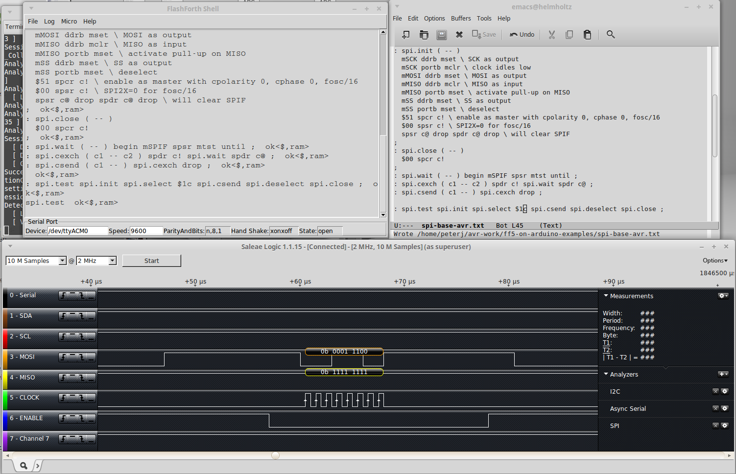
10.3. ATmega328P
\ spi-base-avr.txt
\ Words to drive the SPI module on the ATmega328P
\ PJ 31-Jan-2016
-spi-base
marker -spi-base

\ Registers of interest
$24 constant ddrb
$25 constant portb
$4c constant spcr
$4d constant spsr
$4e constant spdr

\ bit masks
%000100 constant mSS ( PB2 )
%001000 constant mMOSI ( PB3 )
%010000 constant mMISO ( PB4 )
%100000 constant mSCK ( PB5 )
$80 constant mSPIF
$40 constant mWCOL

\ !SS is on PB2
: spi.select ( -- ) mSS portb mclr ;
: spi.deselect ( -- ) mSS portb mset ;

: spi.init ( -- )
  mSCK ddrb mset \ SCK as output
  mSCK portb mclr \ clock idles low
  mMOSI ddrb mset \ MOSI as output
  mMISO ddrb mclr \ MISO as input
  mMISO portb mset \ activate pull-up on MISO
  mSS ddrb mset \ SS as output
  mSS portb mset \ deselect
  $51 spcr c! \ enable as master with cpolarity 0, cphase 0, fosc/16
  $00 spsr c! \ SPI2X=0 for fosc/16
  spsr c@ drop spdr c@ drop \ will clear SPIF
;
: spi.close ( -- )
  $00 spcr c!
;
: spi.wait ( -- ) begin mSPIF spsr mtst until ;
: spi.cexch ( c1 -- c2 ) spdr c! spi.wait spdr c@ ;
: spi.csend ( c1 -- ) spi.cexch drop ;

: spi.test ( -- )
  spi.init
  spi.select
  $1c spi.csend \ an arbitrary byte
  spi.deselect
  spi.close
;
Here is a screenshot showing the record of the SPI communication pins on the ATmega328P
as it sends the single byte 0c, as specified in the spi-test word.
The SPI clock period is 1 microsecond.
10.4. Words to drive a matrix display
Given the base words defined in the previous sections, any of the boards may drive the
matrix display with the following words.
The interesting commands are defined by line 20 and
the disp-test-X words are three examples of doing something with the display.
\ led-matrix-display.txt
\ Drive a MAX7219 display chip with 8x8 LED matrix
-disp-max7219
marker -disp-max7219

: max7219.send ( c1 c2 -- )
  swap spi.select spi.csend spi.csend spi.deselect
;

: disp.normal ( -- ) $0c $01 max7219.send ;
: disp.shutdown ( -- ) $0c $00 max7219.send ;

: disp.test.on ( -- ) $0f $01 max7219.send ;
: disp.test.off ( -- ) $0f $00 max7219.send ;

: disp.no.op ( -- ) $00 $00 max7219.send ;
: disp.intensity ( c -- ) $0a swap max7219.send ;
: disp.decode ( c -- ) $09 swap max7219.send ;
: disp.scan.limit ( c -- ) $0b swap max7219.send ;
: disp.set.digit ( cbits cdigit -- ) swap max7219.send ;

: disp-test-1 ( -- ) \ all LEDs on full, 232mA needed
  spi.init
  disp.test.on
  begin key? until
  disp.test.off
  spi.close
;
: disp-test-2 ( -- ) \ left 4 LEDs on first row, 42mA needed
  spi.init
  disp.normal
  $03 disp.intensity
  $00 disp.scan.limit
  $f0 $01 disp.set.digit
  begin key? until
  disp.shutdown
  spi.close
;
: disp-test-3 ( -- ) \ draw face, 18mA needed
  spi.init
  disp.normal
  $01 disp.intensity
  $07 disp.scan.limit
  %00000000 $01 disp.set.digit
  %01100110 $02 disp.set.digit
  %00000000 $03 disp.set.digit
  %00011000 $04 disp.set.digit
  %00011000 $05 disp.set.digit
  %10000001 $06 disp.set.digit
  %01000010 $07 disp.set.digit
  %00111100 $08 disp.set.digit
  begin key? until
  disp.shutdown
  spi.close
;
11. Communicating with I2C devices
Here are some words for using I2C (or Two-wire) peripherals for each of the microcontrollers in master mode. These words provide abstract the hardware registers and bits to provide a common vocabulary for the interaction with I2C slave devices.
11.1. PIC18FX6K22
\ i2c-base-k22.txt
\ Low-level words for I2C master on PIC18F26K22
\
\ Modelled on the original i2c-base.txt for PIC18,
\ i2c-twi.frt from amforth and
\ the datasheet for Microchip PIC18F26K22.
\ Peter J.  2014-11-08

-i2c-base-k22
marker -i2c-base-k22
hex ram

\ Registers related to I2C operation of MSSP1
$ff3a constant anselc
$ff82 constant portc
$ff8b constant latc
$ff94 constant trisc
$ff9e constant pir1
$ffc5 constant ssp1con2
$ffc6 constant ssp1con1
$ffc7 constant ssp1stat
$ffc8 constant ssp1add
$ffc9 constant ssp1buf
$ffca constant ssp1msk
$ffcb constant ssp1con3

\ Masks for bits
%00000001 constant mSEN \ in ssp1con2
%00000010 constant mRSEN
%00000100 constant mPEN
%00001000 constant mRCEN
%00010000 constant mACKEN
%00100000 constant mACKDT
%01000000 constant mACKSTAT
%00100000 constant mSSP1EN \ in ssp1con1
%00000001 constant mBF \ in ssp1stat
%00001000 constant mSSP1IF \ in pir1

: i2c.init ( -- )
  %00001000 ssp1con1 c! \ Master mode
  [ Fcy #100 / 1- ] literal ssp1add c! \ Set clock frequency to 100 kHz
  mSSP1IF pir1 mclr \ Clear interrupt bit
  %00011000 trisc mset \ SCL1 on RC3, SDA1 on RC4
  %00011000 anselc mclr
  mSSP1EN ssp1con1 mset \ Enable hardware
;

: i2c.close ( -- )
  mSSP1EN ssp1con1 mclr
  mSSP1IF pir1 mclr
;

: i2c.wait ( -- ) \ Wait for interrupt flag and clear it
  begin mSSP1IF pir1 mtst until
  mSSP1IF pir1 mclr
;

: i2c.idle? ( -- f )
  %00011111 ssp1con2 mtst \ ACKEN RCEN REN RSEN SEN
  %100 ssp1stat mtst \ R/^W
  or 0=
;

: i2c.start ( -- ) \ Send start condition
  begin i2c.idle? until
  mSSP1IF pir1 mclr
  mSEN ssp1con2 mset
  i2c.wait
;

: i2c.rsen ( -- ) \ Send repeated start condition
  mSSP1IF pir1 mclr
  mRSEN ssp1con2 mset
  i2c.wait
;

: i2c.stop ( -- ) \ Send stop condition
  mSSP1IF pir1 mclr
  mPEN ssp1con2 mset
  i2c.wait
;

: i2c.buf.full? ( -- f )
  mBF ssp1stat mtst
;

\ Write one byte to bus, leaves ACK bit.
\ A value of 0 indicates ACK was received from slave device.
: i2c.c! ( c -- f )
  begin i2c.buf.full? 0= until
  ssp1buf c!
  begin i2c.buf.full? 0= until
  begin i2c.idle? until
  ssp1con2 c@ mACKSTAT and
;

\ Send ack bit.
: i2c.ack.seq ( -- )
  mACKEN ssp1con2 mset
  begin mACKEN ssp1con2 mtst 0= until
;

\ Read one byte and ack for another.
: i2c.c@.ack ( -- c )
  mRCEN ssp1con2 mset
  begin i2c.buf.full? until
  mACKDT ssp1con2 mclr i2c.ack.seq \ ack
  ssp1buf c@
;

 \ Read one last byte.
: i2c.c@.nack ( -- c )
  mRCEN ssp1con2 mset
  begin i2c.buf.full? until
  mACKDT ssp1con2 mset i2c.ack.seq \ nack
  ssp1buf c@
;

\ Address slave for writing, leaves true if slave ready.
: i2c.addr.write ( 7-bit-addr -- f )
  1 lshift 1 invert and \ Build full byte with write-bit as 0
  i2c.start i2c.c! 0=
;

\ Address slave for reading, leaves true if slave ready.
: i2c.addr.read ( 7-bit-addr -- f )
  1 lshift 1 or \ Build full byte with read-bit as 1
  i2c.start i2c.c! 0=
;

\ Detect presence of device, leaving true if device present, 0 otherwise.
\ We actually fetch a byte if the slave has acknowledged, then discard it.
: i2c.ping? ( 7-bit-addr -- f )
  i2c.addr.read if i2c.c@.nack drop true else false then
;
11.2. PIC24FV32KA30X
\ i2c-base-pic24fv32ka30x.txt
\ Low-level words for I2C master on PIC24FV32KA302 and KA301
\
\ Modelled on i2c-base.txt for PIC18, i2c-twi.frt from amforth
\ the Microchip PIC24 Family Reference Manual
\ and the datasheet for PIC24FV32KA304 family.
\ Peter J.  2015-09-23

-i2c-base
marker -i2c-base
hex ram

\ Registers related to I2C operation of MSSP1
$0086 constant ifs1
$0200 constant i2c1rcv
$0202 constant i2c1trn
$0204 constant i2c1brg
$0206 constant i2c1con
$0208 constant i2c1stat
$020a constant i2c1add
$020c constant i2c1msk
$02c8 constant trisb
$02ca constant portb
$02cc constant latb
$02ce constant odcb
$04e2 constant ansb
$0770 constant pmd1

\ Masks for bits
$8000 constant mI2CEN \ in i2c1con
%000001 constant mSEN
%000010 constant mRSEN
%000100 constant mPEN
%001000 constant mRCEN
%010000 constant mACKEN
%100000 constant mACKDT
$8000 constant mACKSTAT \ in i2c1stat
$4000 constant mTRSTAT
$0400 constant mBCL
$0080 constant mIWCOL
$0040 constant mI2COV
%0001 constant mTBF
%0010 constant mRBF
%0010 constant mMI2C1IF \ in ifs1

$0100 constant mRB8 \ SCL1 on RB8
$0200 constant mRB9 \ SDA1 on RB9

: i2c.init ( -- )
  $80 pmd1 mclr \ Enable the I2C1 module
  [ Fcy #100 / Fcy #10000 / - 1- ] literal i2c1brg c! \ Set clock to 100 kHz
  mMI2C1IF ifs1 mclr \ Clear interrupt bit for master operation
  %1100000000 trisb mset \ SCL1 on RB8, SDA1 on RB9
  %1100000000 odcb mset
  mI2CEN i2c1con mset \ Enable hardware
;

: i2c.close ( -- )
  mI2CEN i2c1con mclr
  mMI2C1IF ifs1 mclr
;

: i2c.bus.reset ( -- )
  \ Manually reset the slave devices.
  \ For use when a slave just won't let SDA1 go.
  i2c.close
  mRB9 trisb mset \ leave SDA1 float
  mRB9 odcb mset
  mRB8 trisb mclr \ drive SCL1 with digital output
  mRB8 odcb mset
  9 for
    mRB8 latb mclr 1 ms
    mRB8 latb mset 1 ms
  next
  \ stop condition
  mRB8 latb mclr
  mRB9 trisb mclr
  mRB9 latb mclr 1 ms
  mRB8 latb mset
  mRB9 latb mset 1 ms
  \ release bus
  mRB8 trisb mset
  mRB9 trisb mset
;

: i2c.wait ( -- ) \ Wait for interrupt flag and clear it
  begin mMI2C1IF ifs1 mtst until
  mMI2C1IF ifs1 mclr
;

: i2c.idle? ( -- f )
  %00011111 i2c1con mtst \ ACKEN RCEN REN RSEN SEN
  0=
;

: i2c.start ( -- ) \ Send start condition
  begin i2c.idle? until
  mMI2C1IF ifs1 mclr
  mSEN i2c1con mset
  i2c.wait
;

: i2c.rsen ( -- ) \ Send repeated start condition
  mMI2C1IF ifs1 mclr
  mRSEN i2c1con mset
  i2c.wait
;

: i2c.stop ( -- ) \ Send stop condition
  mMI2C1IF ifs1 mclr
  mPEN i2c1con mset
  i2c.wait
;

: i2c.tbuf.full? ( -- f )
  mTBF i2c1stat mtst
;

: i2c.rbuf.full? ( -- f )
  mRBF i2c1stat mtst
;

\ Write one byte to bus, leaves ACK bit.
\ A value of 0 indicates ACK was received from slave device.
: i2c.c! ( c -- f )
  begin i2c.tbuf.full? 0= until
  mMI2C1IF ifs1 mclr
  i2c1trn c!
  \ We wait for the interrupt because just waiting for the buffer
  \ to be empty is unreliable if we look too soon.
  i2c.wait
  begin i2c.idle? until
  i2c1stat @ mACKSTAT and
;

\ Send ack bit.
: i2c.ack.seq ( -- )
  mACKEN i2c1con mset
  begin mACKEN i2c1con mtst 0= until
;

\ Read one byte and ack for another.
: i2c.c@.ack ( -- c )
  mRCEN i2c1con mset
  begin i2c.rbuf.full? until
  mACKDT i2c1con mclr i2c.ack.seq \ ack
  i2c1rcv c@
;

 \ Read one last byte.
: i2c.c@.nack ( -- c )
  mRCEN i2c1con mset
  begin i2c.rbuf.full? until
  mACKDT i2c1con mset i2c.ack.seq \ nack
  i2c1rcv c@
;

\ Address slave for writing, leaves true if slave ready.
: i2c.addr.write ( 7-bit-addr -- f )
  1 lshift 1 invert and \ Build full byte with write-bit as 0
  i2c.start i2c.c! 0=
;

\ Address slave for reading, leaves true if slave ready.
: i2c.addr.read ( 7-bit-addr -- f )
  1 lshift 1 or \ Build full byte with read-bit as 1
  i2c.start i2c.c! 0=
;

\ Detect presence of device,
\ leaving true if device present, 0 otherwise.
\ We actually fetch a byte if the slave has acknowledged.
: i2c.ping? ( 7-bit-addr -- f )
  i2c.addr.read if i2c.c@.nack drop true else false then
;
11.3. ATmega328P
\ i2c-base-avr.txt
\ Low-level words for TWI/I2C on Atmega328P.
\
\ Modelled on i2c-twi.frt from amforth,
\ i2c_base.txt for FlashForth on PIC18
\ and the Atmel datasheet, of course.
\ Peter J.  2014-10-27

-i2c-base
marker -i2c-base
hex ram

\ Two-Wire-Interface Registers
$b8 constant TWBR
$b9 constant TWSR
$bb constant TWDR
$bc constant TWCR

\ Bits in the Control Register
%10000000 constant mTWINT
%01000000 constant mTWEA
%00100000 constant mTWSTA
%00010000 constant mTWSTO
%00001000 constant mTWWC
%00000100 constant mTWEN
%00000001 constant mTWIE

: i2c.init ( -- ) \ Set clock frequency to 100kHz
  %11 TWSR mclr \ prescale value = 1
  [ Fcy #100 / #16 - 2/ ] literal TWBR c!
  mTWEN TWCR mset
;

: i2c.wait ( -- ) \ Wait for operation to complete
  \ When TWI operations are done, the hardware sets
  \ the TWINT interrupt flag, which we will poll.
  begin TWCR c@ mTWINT and until
;

: i2c.start ( -- ) \ Send start condition
  [ mTWINT mTWEN or mTWSTA or ] literal TWCR c!
  i2c.wait
;

: i2c.rsen ( -- ) \ Send repeated start condition
  i2c.start \ AVR doesn't distinguish
;

: i2c.stop ( -- ) \ Send stop condition
  [ mTWINT mTWEN or mTWSTO or ] literal TWCR c!
;

\ Write one byte to bus, returning 0 if ACK was received, -1 otherwise.
: i2c.c! ( c -- f )
  i2c.wait \ Must have TWINT high to write data
  TWDR c!
  [ mTWINT mTWEN or ] literal TWCR c!
  i2c.wait
  \ Test for arrival of an ACK depending on what was sent.
  TWSR c@ $f8 and $18 xor 0= if 0 exit then \ SLA+W
  TWSR c@ $f8 and $28 xor 0= if 0 exit then \ data byte
  TWSR c@ $f8 and $40 xor 0= if 0 exit then \ SLA+R
  -1 \ Something other than an ACK resulted
;

\ Read one byte and ack for another.
: i2c.c@.ack ( -- c )
  [ mTWINT mTWEN or mTWEA or ] literal TWCR c!
  i2c.wait
  TWDR c@
;

\ Read one last byte.
: i2c.c@.nack ( -- c )
  [ mTWINT mTWEN or ] literal TWCR c!
  i2c.wait
  TWDR c@
;

\ Address slave for writing, leaving true if slave ready.
: i2c.addr.write ( 7-bit-addr -- f )
  1 lshift 1 invert and \ Build full byte with write-bit as 0
  i2c.start i2c.c! if false else true then
;

\ Address slave for reading, leaving true if slave ready.
: i2c.addr.read ( 7-bit-addr -- f )
  1 lshift 1 or \ Build full byte with read-bit as 1
  i2c.start i2c.c! if false else true then
;

\ Detect presence of device, leaving true if slave responded.
\ If the slave ACKs the read request, fetch one byte only.
: i2c.ping? ( 7-bit-addr -- f )
  1 lshift 1 or \ Build full byte with read-bit as 1
  i2c.start i2c.c! 0= if i2c.c@.nack drop true else false then
;
11.4. Notes on using the words
-
The word
i2c.initis used to set up the I2C master peripheral for further activities. -
I2C conversations begin by addressing a slave device for either reading or writing. The words
i2c.addr.readandi2c.addr.writeare provided for this waking of the slave. They leave a flag on the stack to indicate whether the slave device acknowledged being addressed. If the slave device responded appropriately, you may proceed to read or write bytes. -
There are two words for reading a byte from the bus.
i2c.c@.ackreads a byte and asserts an acknowledge (ACK) to indicate to the slave device that another byte will be read subsequently.i2c.c@.nackreads a byte and asserts a NACK to indicate to the slave that no more bytes are wanted. -
The word to send a byte to the slave device is
i2c.c!. This word leaves a flag to indicate the state of the ACK bit following the action of sending the byte. If the slave asserted ACK, the flag will be0. You maydropthis flag if it not of interest to you. -
There are lower-level words
i2c.start,i2c.rsenandi2c.stopto assert start, restart and stop conditions respectively. These are used within the higher-level words mentioned above. -
The utility word
i2c.ping?attempts to address a slave and read a byte. It leavestrueif the slave responds, elsefalse. -
Sometimes when tinkering with a new I2C device, you can get into a state of confusion such that the slave device will end up in some intermediate state waiting for clock signals. (This happens more often than I would like to admit.) In this state, the slave device will no longer respond in a way that the master peripheral understands. Rather than cycle the power to reset the slave device, it may be convenient to force the clocking of the data bits through the bus and get the slave device back into an idle state. The word
i2c.reset.bus(ini2c-base-pic24fv32ka30x.txt) is provided to automate this forced clocking.
11.5. Detecting I2C devices
Building on the base words for a particular microcontroller, the following program works on all of the microcontrollers discussed in this tutorial guide. It is convenient to run this program to to see if the device of interest is responding. There’s no point trying to have a conversation with a device that doesn’t respond to being addressed.
\ i2c-detect.txt
\ Detect presence of all possible devices on I2C bus.
\ Only the 7 bit address schema is supported.
\
\ Copied from amForth distribution (lib/hardware/)
\ and lightly edited to suit FlashForth 5.0 on AVR.
\ Builds upon i2c-base-xxxx.txt and doloop.txt.
\ Peter J. 2014-10-27

-i2c-detect
marker -i2c-detect

\ not all bitpatterns are valid 7bit i2c addresses
: i2c.7bitaddr? ( a -- f)  $7 $78 within ;

: i2c.detect   ( -- )
    base @ hex
    \ header line
    cr 5 spaces $10 0 do i 2 u.r loop
    $80 0 do
      i $0f and 0= if
        cr i 2 u.r [char] : emit space
      then
      i i2c.7bitaddr? if
        i i2c.ping? if \ does device respond?
            i 2 u.r
          else
            ." -- "
        then
      else
         ."    "
      then
    loop
    cr base !
;

\ With a lone Microchip TC74A0 sitting on the bus,
\ the output looks like
\ i2c.init  ok<$,ram>
\ i2c.detect
\      00 01 02 03 04 05 06 07 08 09 0a 0b 0c 0d 0e 0f
\ 00 :                      -- -- -- -- -- -- -- -- --
\ 10 : -- -- -- -- -- -- -- -- -- -- -- -- -- -- -- --
\ 20 : -- -- -- -- -- -- -- -- -- -- -- -- -- -- -- --
\ 30 : -- -- -- -- -- -- -- -- -- -- -- -- -- -- -- --
\ 40 : -- -- -- -- -- -- -- -- 48 -- -- -- -- -- -- --
\ 50 : -- -- -- -- -- -- -- -- -- -- -- -- -- -- -- --
\ 60 : -- -- -- -- -- -- -- -- -- -- -- -- -- -- -- --
\ 70 : -- -- -- -- -- -- -- --
\  ok<$,ram>
\ i2c.stop  ok<$,ram>
12. Using I2C to get temperature measurements
Using the words in i2c-base-k22.txt to control the MSSP peripheral in master mode,
one may talk to the TC74A5 temperature measurement chip on the PICDEM 2 PLUS
and report sensor temperature.
\ Read temperature from TC74 on PICDEM2+ board with PIC18F46K22-I/P.
\ Modelled on Mikael Nordman's i2c_tcn75.txt.
\ This program requires i2c-base-k22.txt to be previously loaded.
-read-tc74
marker -read-tc74

%1001101 constant addr-TC74A5  \ 7-bit address for the chip

: tc74-init ( -- )
  \ Selects the temperature register for subsequent reads.
  addr-TC74A5 i2c.addr.write if 0 i2c.c! drop then i2c.stop
;
: sign-extend ( c -- n )
  \ If the TC74 has returned a negative 8-bit value,
  \ we need to sign extend to 16-bits with ones.
  dup $7f > if $ff80 or then
;
: degrees@ ( -- n )
  \ Wake the TC74 and receive its register value.
  addr-TC74A5 i2c.addr.read if i2c.c@.nack sign-extend else 0 then
;
: tc74-main ( -- )
  i2c.init
  tc74-init
  begin
    degrees@ .
    #1000 ms
  key? until
;

\ Now, report temperature in degrees C
\ while we warm up the TC74 chip with our fingers...
decimal tc74-main
With a Saleae Logic Analyser connected to the pins of the TC74A5, we can see the I2C
signals as a result of calling the tc74-init word.

A little later on, the degrees@ word is invoked.
The returned binary value of 0b00010101 corresponds
to the very pleasant 21oC that existed in the back shed as this text was being written.

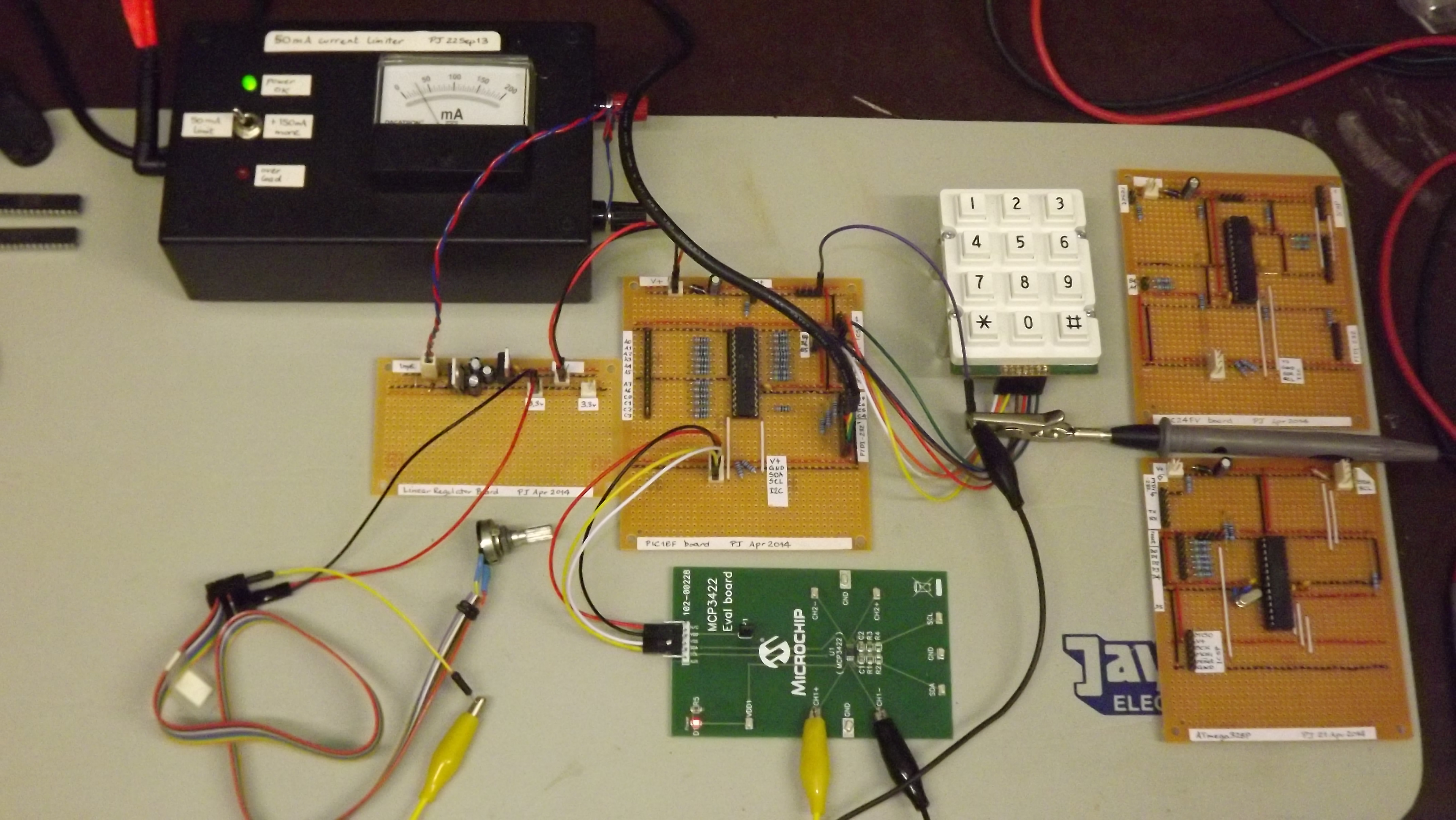
13. Making high-resolution voltage measurements
The Microchip MCP3422 is a \x03A3;\x0394;-ADC that can connected via I2C port. This neat little converter can measure voltages with a resolution of 18 bits (at the lowest data rate of 3.75 samples per second) and includes a programmable gain amplifier. Being available in a surface-mount package only, it was convenient to use a prebuilt evaluation board, the green board between the home-built FlashForth demo board and the fixed-voltage supply board. The MCP3422 evaluation board is connected to and powered from the I2C header on the FlashForth demo board. Separately, the fixed-voltage supply board provides the measurement voltage to channel 1 of the MCP3422 via a potentiometer that is set to give 1.024 V, according to my (fairly cheap) multimeter.
\ mcp3422-2016.txt
\ Play with mcp3422 eval board.
\ PJ, 21-Oct-2013
\     28-Apr-2014 PIC18F26K22 version
\     27-Jan-2016 update to use latest i2c words
\ Needs i2c-base-k22.txt and math.txt (to get m*/).

-mcp3422
marker -mcp3422

$68 constant addr-mcp3422 \ 7-bit address

: mcp3422-init ( -- )
  \ $9c is config for 18-bit continuous conversions of ch 1
  addr-mcp3422 i2c.addr.write if $9c i2c.c! drop then i2c.stop
;

: mcp3422@ ( -- d f ) \ Read the 18-bit result as 3 bytes
  addr-mcp3422 i2c.addr.read
  if
    i2c.c@.ack                         \ only 2 bits in first byte
    dup $3 > if $fffa or then          \ sign-extend to full cell
    i2c.c@.ack $8 lshift i2c.c@.ack or \ next two bytes into one cell
    swap                               \ leave double result
    i2c.c@.nack $80 and 0=             \ leave true if result is latest
  else
    0 0 0  \ device did not ack on address
  then
;

: microvolts ( d1 -- d2 )
  \ The least-significant bit corresponds to 15.625 microvolts
  #125 #8 m*/
;

: (d.3) ( d -- )
  swap over dabs
  <# # # # [char] . hold #s rot sign #>
;

: report ( d f -- ) \ Assuming decimal, print millivolt value
  cr if ." new " else ." old " then
  microvolts (d.3) type space ." mV "
;

: mcp3422-run ( -- )
  decimal
  i2c.init mcp3422-init
  begin
    mcp3422@ report
    #1000 ms
  key? until
  hex
;
Notes on this program:
-
mcp3422-runis the top-level word that initializes the hardware, then periodically reads the MCP3422 data and reports the voltage (in millivolts) to the user terminal. The program runs until a key is pressed. -
The converted value is read from the MCP3422 as an 18-bit value in 2-complement format. The word
mcp3422@reads the data as three bytes from the I2C port and then shuffles it into a double-cell value that is left on the stack, along with a flag to indicate whether the value sent by the MCP3422 happened to be the latest data. If the MCP3422 did not respond to being addressed, zeros will be left on the stack in place of the expected data. -
The value is scaled to microvolts and then the resultant double value is output using the pictured numeric output to have 3 decimal places so that it looks like a millivolt reading. Several lines from the terminal look like the following:
new 1028.031 mV
new 1028.062 mV
new 1028.046 mV
-
This program builds upon the
i2c-base-k22words in order to communicate with the MCP3422. The code for scaling of the measured data requires the mixed-scale wordm*/from the filemath.fsprovided by FlashForth.
14. An I2C slave example
The MSSP in the PIC18F26K22 can also be used in slave mode. Here, the FlashForth demo board is presented as an I2C slave device to an Aardvark serial interface, acting as master. The UART communication is provided by a Future Technology Devices International USB TTL-serial cable.
The core of the program is the i2c_service word which is invoked
each time a serial-port event is flagged by the SSPIF bit in the PIR1 flag register.
This word is an implementation of the state look-up approach detailed in
the Microchip Application Note AN734
Using the PIC Devices’ SSP and MSSP Modules for Slave I2C Communication.
The rest of the program is there to provide (somewhat) interesting data
for the I2C master to read and to do something (light a LED)
when the master writes suitable data to the slave.
-i2c-slave
marker -i2c-slave
\ Make the FlashForth 26K22 demo board into an I2C slave.
\ An I2C master can read and write to a buffer here,
\ the least-significant bit of the first byte controls
\ the LED attached to pin RB0.
\
\ Needs core.txt loaded.

$ff81 constant portb
$ff82 constant portc
$ff8a constant latb
$ff93 constant trisb
$ff94 constant trisc
$ff3a constant anselc

: led_on ( -- )
  %00000001 latb mset
;
: led_off ( -- )
  %00000001 latb mclr
;
: err_led_on ( -- )
  %00000010 latb mset
;
: err_led_off ( -- )
  %00000010 latb mclr
;

\ Establish a couple of buffers in RAM, together with index variables.
ram
8 constant buflen
\ Receive buffer for incoming I2C data.
create rbuf buflen allot
variable rindx
: init_rbuf ( -- )
  rbuf buflen erase
  0 rindx !
;
: incr_rindx ( -- ) \ increment with wrap-around
  rindx @ 1 +
  dup buflen = if drop 0 then
  rindx !
;
: save_to_rbuf ( c -- )
  rbuf rindx @ + c!
  incr_rindx
;

\ Send buffer with something interesting for the I2C master to read.
create sbuf buflen allot
variable sindx
: incr_sindx ( -- ) \ increment with wrap-around
  sindx @ 1 +
  dup buflen = if drop 0 then
  sindx !
;
: init_sbuf ( -- ) \ fill with counting integers, for interest
  buflen
  for
    r@ 1+
    sbuf r@ + c!
  next
  0 sindx !
;

\ I2C-related definitions and code
$ffc5 constant sspcon2
$ffc6 constant sspcon1
$ffc7 constant sspstat
$ffc8 constant sspadd
$ffc9 constant sspbuf
$ff9e constant pir1

\ PIR1 bits
%00001000 constant sspif

\ SSPSTAT bits
%00000001 constant bf
%00000100 constant r_nw
%00001000 constant start_bit
%00010000 constant stop_bit
%00100000 constant d_na
%01000000 constant cke
%10000000 constant smp

d_na start_bit or r_nw or bf or constant stat_mask

\ SSPCON1 bits
%00010000 constant ckp
%00100000 constant sspen
%01000000 constant sspov
%10000000 constant wcol

\ SSPCON2 bits
%00000001 constant sen

: i2c_init ( -- )
  %11000 anselc mclr \ enable digital-in on RC3,RC4 (SCL1,SDA1)
  %00011000 trisc mset \ RC3==SCL RC4==SDA
  %00000110 sspcon1 c! \ Slave mode with 7-bit address
  sen sspcon2 mset \ Clock stretching enabled
  smp sspstat mset \ Slew-rate disabled
  $52 1 lshift sspadd c! \ Slave address
  sspen sspcon1 mset \ Enable MSSP peripheral
;

: release_clock ( -- )
  ckp sspcon1 mset
;

: i2c_service ( -- )
  \ Check the state of the I2C peripheral and react.
  \ See App Note 734 for an explanation of the 5 states.
  \
  \ State 1: i2c write operation, last byte was address.
  \ D_nA=0, S=1, R_nW=0, BF=1
  sspstat c@ stat_mask and %00001001 =
  if
    sspbuf @ drop
    init_rbuf
    release_clock
    exit
  then
  \ State 2: i2c write operation, last byte was data.
  \ D_nA=1, S=1, R_nW=0, BF=1
  sspstat c@ stat_mask and %00101001 =
  if
    sspbuf c@ save_to_rbuf
    release_clock
    exit
  then
  \ State 3: i2c read operation, last byte was address.
  \ D_nA=0, S=1, R_nW=1
  sspstat c@ %00101100 and %00001100 =
  if
    sspbuf c@ drop
    0 sindx !
    wcol sspcon1 mclr
    sbuf sindx @ + c@ sspbuf c!
    release_clock
    incr_sindx
    exit
  then
  \ State 4: i2c read operation, last byte was outgoing data.
  \ D_nA=1, S=1, R_nW=1, BF=0
  sspstat c@ stat_mask and %00101100 =
  ckp sspcon1 mtst 0=
  and
  if
    wcol sspcon1 mclr
    sbuf sindx @ + c@ sspbuf c!
    release_clock
    incr_sindx
    exit
  then
  \ State 5: master NACK, slave i2c logic reset.
  \ From AN734: D_nA=1, S=1, BF=0, CKP=1, however,
  \ we use just D_nA=1 and CKP=1, ignoring START bit.
  \ This is because master may have already asserted STOP
  \ before we service the final NACK on a read operation.
  d_na sspstat mtst 0 > ckp sspcon1 mtst 0 > and
  stop_bit sspstat mtst or
  if
    exit \ Nothing needs to be done.
  then
  \ We shouldn't arrive here...
  err_led_on
  cr ." Error "
  ." sspstat " sspstat c@ u.
  ." sspcon1 " sspcon1 c@ u.
  ." sspcon2 " sspcon2 c@ u.
  cr
  begin again \ Hang around until watch-dog resets MCU.
;


: init ( -- )
  %00000011 trisb mclr  \ want RB0,RB1 as output pins
  init_rbuf
  init_sbuf
  i2c_init
  led_on err_led_on #200 ms led_off err_led_off
;

: main ( -- )
  cr ." Start I2C slave "
  init
  begin
    sspif pir1 mtst
    if
      sspif pir1 mclr
      i2c_service
    then
    rbuf c@ %00000001 and
    if led_on else led_off then
    cwd
  key? until
;

\ ' main is turnkey
With a Saleae Logic Analyser connected, we can see the I2C
signals as a result of writing the byte 0x01 to turn on the LED.
The following figure shows the data and clock signals from the time that the
master asserts the START condition (green circle)
until it asserts the STOP condition (as indicated by the red square).

The clock frequency is 100 kHz and there is a 138 microsecond gap between the ninth clock pulse of the address byte and the start of the pulses for the data byte. This gives an indication of the time needed to service each SSPIF event.
A little later on, the Aardvark reads two bytes from the bus, as shown here.

Zooming in, to show the finer annotation, the same signals are shown below.


Again, the inter-byte gap is 138 microseconds resulting in about 200 microseconds needed to transfer each byte. This effective speed of 5 kbytes/s should be usable for many applications, since the I2C bus is typically used for low speed data transfer.
Notes on this program:
-
Need to load
core.fsbefore the source code of thei2c-slave.txt. -
Slave examples found in documentation on the Web usually have the service function written in the context of an interrupt service routine. The MSSP can be serviced quite nicely without resorting to the use of interrupts, however, you still have to check and clear the SSPIF bit for each event.
-
The implementation of the test for State 5 (Master NACK) is slightly different to that described in AN734 because it was found that the master would assert an I2C bus stop after the final NACK of a read operation but before the MCU could service the SSPIF event. This would mean that STOP was the most recent bus condition seen by the MSSP and the START and STOP bits set to reflect this. In the figures shown above, there is only about 12 microseconds between the ninth clock pulse for the second read data byte and the Aardvark master asserting the STOP condition on the bus. This period is very much shorter than the (approx.) 140 microseconds period needed by the slave firmware to service the associated SSPIF event.
15. Speed of operation — bit banging
All of this nice interaction and convenience has some costs.
One cost is the number of MCU instruction cycles needed to process
the Forth words.
To visualize this cost, the following program defines a word blink-forth which
toggles an IO pin using the high-level FlashForth words that fetch and store bit patterns into the
port latch register.
An alternative word blink-asm uses assembler instructions to achieve an equivalent effect, but faster,
and a third word blink-bits uses the FlashForth bit0: and bit1: words
to create high-level bit-manipulation words that also achieve full machine speed.
15.1. PIC18F26K22
-speed-test
marker -speed-test
\ Waggle RB1 as quickly as we can, in both high- and low-level code.
\ Before sending this file, we should send asm.txt so that we have
\ the clrwdt, word available.  We also need bit.txt.

$ff8a constant latb
$ff93 constant trisb

: initRB1
  %10 trisb mclr \ RB1 as output
  %10 latb mclr \ initially known state
;

\ high-level bit fiddling, presumably slow
: blink-forth ( -- )
  initRB1
  begin
    %10 latb c! 0 latb c! \ one cycle, on and off
    %10 latb c! 0 latb c!
    %10 latb c! 0 latb c!
    %10 latb c! 0 latb c!
    cwd \ We have to kick the watch dog ourselves.
  again
;

\ low-level bit fiddling, via assembler
: blink-asm ( -- )
  initRB1
  [
  begin,
    latb 1 a, bsf,  latb 1 a, bcf, \ one cycle, on and off
    latb 1 a, bsf,  latb 1 a, bcf,
    latb 1 a, bsf,  latb 1 a, bcf,
    latb 1 a, bsf,  latb 1 a, bcf,
    clrwdt, \ kick the watch dog
  again,
  ]
;

\ high-level bit fiddling with named bits
latb #1 bit1: RB1-hi inlined
latb #1 bit0: RB1-lo inlined
: blink-bits ( -- )
  initRB1
  begin
    RB1-hi RB1-lo \ one cycle
    RB1-hi RB1-lo
    RB1-hi RB1-lo
    RB1-hi RB1-lo
    cwd
  again
;
Notes on this program:
-
We have had to worry about clearing the watch-dog timer. In the early examples, the FlashForth interpreter was passing through the pause state often enough to keep the watch-dog happy. The words in this example give the FlashForth interpreter no time to pause so we are responsible for clearing the watch-dog timer explicitly.
-
In the source code config file for the specific MCU, the watch-dog timer postscale is set to 256. With a 31.25 kHz oscillator frequency, this leads to a default timeout period of a little over 1 second (32 microseconds X 128 X 256).
-
For the PIC18 MCU, the internal oscillator of 16 MHz was multiplied by the PLL to get 64 MHz oscillator driving the MCU. With 4 clock cycles per instruction cycle, this gave an instruction period TCY = 62.5 nanoseconds. Current consumption by the microcontroller was about 14 mA, roughly double the value when the interpreter is not doing much, just waiting for input.
-
The first screen image below shows the output signal for running the high-level
blink-forthword while the second image uses the assembler words.
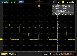
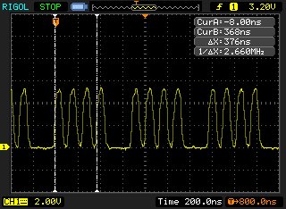
-
For the
blink-forthword, one on+off cycle of the LED executes in 6 words and is seen (in the oscilloscope record) to require about 50 instruction cycles. So, on average, each of these threaded Forth words is executed in about 8 MCU instruction cycles. Note that this overhead includes the cost of using 16-bit cells for the data. Extra machine instructions are used to handle the upper bytes. In other applications, where we actually want to handle 16-bit data, this will no longer be a penalty. -
The assembler version has no overhead and the cycle time for the MCU instructions defines the period of the output signal. One on-off cycle requires 2 instructions so we see a short 125 nanosecond period. This is fast enough that the capacitive loading on the output pin is noticeable in the oscilloscope trace. Also, the time required for the machine instructions to clear the watch-dog timer and the instruction jump back to the start of the loop now shows up clearly in the oscilloscope record.
-
The oscilloscope record for the
blink-bitsword is shown here. With the bit-manipulation wordsRB1-hiandRB1-lobeing inlined, they also achieve full machine speed because the generated code is essentially the same as forblink-asm.
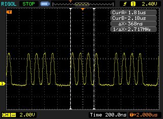
15.2. PIC24FV32KA302
-speed-test
marker -speed-test
\ For the PIC24FV32KA302, waggle RB15 as quickly as we can,
\ in both high- and low-level code.
\ Remember to load bit.txt before this file.

$02c8 constant trisb
$02ca constant portb
$02cc constant latb
$02ce constant odcb

1 #15 lshift constant bit15

: initRB15
  bit15 trisb mclr \ RB15 as output
  bit15 latb mclr \ initially known state
;

\ high-level bit fiddling, presumably slow
: blink-forth ( -- )
  initRB15
  begin
    bit15 latb ! 0 latb ! \ one cycle, on and off
    bit15 latb ! 0 latb !
    bit15 latb ! 0 latb !
    bit15 latb ! 0 latb !
    cwd \ We have to kick the watch dog ourselves.
  again
;

\ low-level bit fiddling, via assembler
: blink-asm ( -- )
  initRB15
  [
  begin,
    #15 latb bset,  #15 latb bclr, \ one cycle, on and off
    #15 latb bset,  #15 latb bclr,
    #15 latb bset,  #15 latb bclr,
    #15 latb bset,  #15 latb bclr,
    ] cwd [ \ kick the watch dog
  again,
  ]
;

\ high-level bit fiddling with named bits
latb #15 bit1: RB15-hi inlined
latb #15 bit0: RB15-lo inlined
: blink-bits ( -- )
  initRB15
  begin
    RB15-hi RB15-lo \ one cycle
    RB15-hi RB15-lo
    RB15-hi RB15-lo
    RB15-hi RB15-lo
    cwd
  again
;
Notes on this program:
-
The order of the assembler arguments is bit-number register-address op-code. This is different to that seen in the PIC18 version of the program.
-
The MCU was configured for running off its internal 8 MHz oscillator with the 4X PLL active and a 1:1 postscaling. This resulted in an instruction cycle period TCY = 62.5 nanoseconds.
-
The first screen image below shows the output signal for running the high-level
blink-forthword while the second image uses the assembler words.
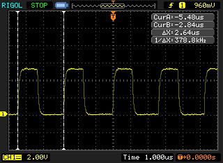
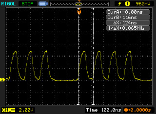
-
For the
blink-forthword, one on+off cycle of the LED executes in 6 words and is seen (in the oscilloscope record) to require about 42 instruction cycles. So, on average, each of these threaded Forth words is executed by the 16-bit PIC24 in 7 MCU instruction cycles. This illustrates a benefit of the 16-bit processor, since the 8-bit PIC18F26K22 required 50 MCU instruction cycles (and a correspondingly longer time of 3.08 microseconds) for the same effect. -
The assembler version has no overhead and the cycle time for the MCU instructions defines the period of the output signal. One on-off cycle requires 2 instructions so we see a short 124 nanosecond period.
-
The oscilloscope record for the
blink-bitsword is shown here. Again, the bit-manipulation wordsRB15-hiandRB15-loalso achieve full machine speed.
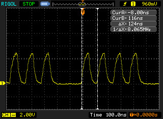
15.3. ATmega328P
-speed-test
marker -speed-test
\ Waggle PB5 as quickly as we can, in both high- and low-level code.
\ Before sending this file, we should send asm.txt and bit.txt.

$0024 constant ddrb
$0025 constant portb    \ RAM address
$0005 constant portb-io \ IO-space address
1 #5 lshift constant bit5

: initPB5
  bit5 ddrb mset \ set pin as output
  bit5 portb mclr \ initially known state
;

: cwd ( -- ) [ wdr, ] ; inlined \ we might want to reset the watchdog

\ high-level bit fiddling, presumably slow
: blink-forth ( -- )
  initPB5
  begin
    bit5 portb c! 0 portb c! \ one cycle, on and off
    bit5 portb c! 0 portb c!
    bit5 portb c! 0 portb c!
    bit5 portb c! 0 portb c!
    cwd
  again
;

\ low-level bit fiddling, via assembler
: blink-asm ( -- )
  initPB5
  [
  begin,
    portb-io #5 sbi,  portb-io #5 cbi, \ one cycle, on and off
    portb-io #5 sbi,  portb-io #5 cbi,
    portb-io #5 sbi,  portb-io #5 cbi,
    portb-io #5 sbi,  portb-io #5 cbi,
    wdr,
  again,
  ]
;

\ high-level bit fiddling with named bits
portb #5 bit1: PB5-hi inlined
portb #5 bit0: PB5-lo inlined
: blink-bits ( -- )
  initPB5
  begin
    PB5-hi PB5-lo \ one cycle
    PB5-hi PB5-lo
    PB5-hi PB5-lo
    PB5-hi PB5-lo
    cwd
  again
;
Notes on this program:
-
Except for names, this code is essentially the same as for the PIC18 and PIC24 versions of the exercise. FlashForth abstracts away much of the instruction-set architecture of the microcontroller, leaving us to focus on twiddling the bits of the peripheral hardware.
-
The MCU was configured for running with the 16 MHz crystal, which resulted in a machine clock cycle period TCY = 62.5 nanoseconds.
-
The first screen image below shows the output signal for running the high-level
blink-forthword while the second image uses the assembler words.
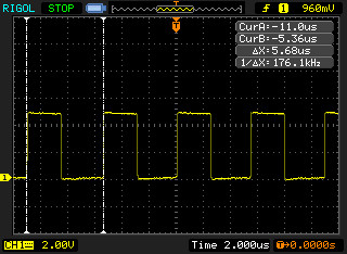
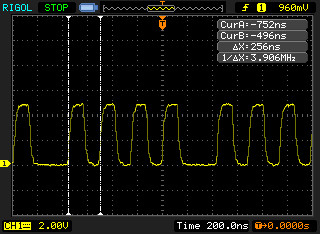
-
For the
blink-forth, one on+off cycle of the LED executes in 6 words and is seen (in the oscilloscope record) to require about 90 instruction cycles. So, on average, each of these threaded Forth words is executed by the 8-bit AVR in 15 MCU instruction cycles. -
The assembler version has no overhead and the cycle time for the MCU instructions defines the period of the output signal. One on-off cycle requires 2 instructions (
sbiand \verb!cbi!) each requiring 2 clock cycles, so we see a short, quarter-microsecond period. -
The oscilloscope record for the \verb!blink-bits! word is shown here. It can be seen that the bit-manipulation words
PB5-hiandPB5-loachieve full machine speed.
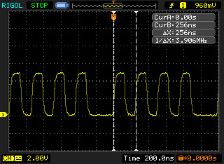
16. Driving an Hitachi-44780 LCD controller
The LCD in the photograph in the Development Boards section was driven with the following code. During the development of this example, a lesson was relearned — that of reading the data sheet 😉
\ Exercise LCD on PICDEM2+ board.
\ Remember to load bit.txt before this file.
-xlcd
marker -xlcd

$ff80 constant porta
$ff89 constant lata
$ff92 constant trisa
$ff83 constant portd
$ff8c constant latd
$ff95 constant trisd

\ The LCD is operated in nibble mode.
\ RA1 = Enable (E) pin
\ RA2 = Read/Write (RW) pin
\ RA3 = Register Select (RS) pin
\ RD0 = DB4 on LCD
\ RD1 = DB5
\ RD2 = DB6
\ RD3 = DB7

portd constant dataport
lata #1 bit0: Elo
lata #1 bit1: Ehi
lata #2 bit0: RWlo
lata #2 bit1: RWhi
lata #3 bit0: RSlo
lata #3 bit1: RShi

: data-port-in ( -- )
  trisd c@ $0f or trisd c!
;

: data-port-out ( -- )
  trisd c@ $f0 and trisd c!
;

: put-nibble ( c -- )
  \ Make lower 4 bits of c appear on data port pins.
  $0f and
  dataport c@ $f0 and
  or
  dataport c!
;

: short-delay ( -- )
  18 for r@ drop next ;

: Estrobe ( -- )
  Ehi short-delay Elo
;

: lcd-getc ( -- c )
  \ Read the LCD register in two nibbles.
  \ Remember to select the register line before calling this word.
  data-port-in
  RWhi short-delay
  Ehi short-delay dataport c@ #4 lshift Elo short-delay \ high nibble
  Ehi short-delay dataport c@ Elo short-delay \ low nibble
  or \ assemble full byte and leave it on the stack
  RWlo short-delay
;

: lcd-ready? ( -- f )
  \ Read the command register and check busy bit.
  RSlo short-delay
  lcd-getc $80 and 0=
;

: wait-for-lcd ( -- )
  begin lcd-ready? cwd until
;

: lcd-putc ( c -- )
  \ Write the LCD register in two nibbles.
  \ Remember to select the register line before calling this word.
  dup $f0 and #4 rshift \ high nibble left on top of stack
  data-port-out
  RWlo short-delay
  put-nibble short-delay Estrobe short-delay
  $0f and \ low nibble now left on top of stack
  put-nibble short-delay Estrobe short-delay
  data-port-in
;

: lcd-clear ( -- )
  wait-for-lcd
  RSlo short-delay
  %00000001 lcd-putc
;

: lcd-home ( -- )
  wait-for-lcd
  RSlo short-delay
  %00000010 lcd-putc
;

: lcd-goto ( c -- )
  \ Set the specified 7-bit data memory address.
  wait-for-lcd
  RSlo short-delay
  $80 or \ sets the highest bit for the command
  lcd-putc
;

: lcd-init ( -- )
  data-port-in
  Elo RWlo RSlo
  %00001110 trisa mclr \ RS, RW and E as output
  30 ms \ power-on delay
  \ Begin "initialization by instruction"
  \ Presumably, the LCD is in 8-bit interface mode.
  %0011 put-nibble Estrobe 5 ms
  %0011 put-nibble Estrobe 1 ms
  %0011 put-nibble Estrobe 1 ms
  \ Function set for 4-bit interface; it is still in 8-bit mode.
  %0010 put-nibble Estrobe 1 ms
  \ Now, we should be in 4-bit interface mode.
  \ Function set for 4-bit interface, 2 display lines 5x7 font.
  wait-for-lcd
  %00101000 lcd-putc
  \ Increment cursor after each byte, don't shift display.
  wait-for-lcd
  %00000110 lcd-putc
  \ Display off
  wait-for-lcd
  %00001000 lcd-putc
  \ Display clear
  %00000001 lcd-putc
  5 ms
  \ End of "initialization by instruction"
  \ Enable cursor and display, no blink.
  wait-for-lcd
  %00001110 lcd-putc 1 ms
  wait-for-lcd
;

: lcd-emit ( c -- ) \ Write the byte into data memory.
  wait-for-lcd
  RShi short-delay
  lcd-putc
;

: lcd-type ( c-addr n -- ) \ send string
  for c@+ lcd-emit next
  drop
;

: main
  ." Begin..."
  lcd-init
  cr ." lcd-init done."
  s" Hello from" lcd-type
  $40 lcd-goto
  s" FlashForth 5.0" lcd-type
  cr ." exercise done."
;
References
-
[1] Brodie, L. and Forth Inc. (1987) Starting Forth: An introduction to the Forth Language and operating system for beginners and professionals, 2nd Ed. Prentice Hall ISBN 0-13-843079-9. Also, updated and online http://home.iae.nl/users/mhx/sf.html and the official online version http://www.forth.com/starting-forth/
-
[2] Conklin, E. K. and Rather, E. D. (2007) Forth Programmer’s Handbook, 3rd Ed. Forth Inc. ISBN 1-4196-7549-4
-
[3] Pelc, S. (2011). Programming Forth. Microprocessor Engineering Limited, ISBN 978-0-9525310-5-0. http://www.mpeforth.com/